


see Part 1 here
In last month’s installment of this series, we discussed how vibration monitoring is an affordable and reliable component for almost any manufacturing concern and introduced some common Metrix customer questions related to our DPS 1 system. Below, concluding this series, we’ll address more common questions on getting the most out of your proximity devices. From verification reports to custom calibration to comparison against an analog driver or transmitter, there’s still a great deal to learn—so let’s get started.
HOW IS THE PROXIMITY SYSTEM “VERIFICATION” DONE WITH THE DPS 1.35?
Using the Metrix DPS configuration and utility software, connected to a DPS unit, while using the “Verification” tab the DPS proximity probe system can be verified to a known target material. This process can be completed by using a proximity probe static calibrator (dial micrometer) looking at shaft target material or the shaft directly.
When the proper gap is set between the probe and appropriate target material in 10 mil or 250 micron increments, use the “Get” button for the DPS to gather the voltage information. Please note that this process takes between 5 and 10 seconds, and cannot be filled in. It must be the voltage measured by the Metrix Digital Proximity System 1.35.
As the gaps are changed and voltages recorded the system draws the line between points, calculates the incremental scale factor (IFS—slope between points), the average scale factor (ASF), and the deviation from straight line (DSL—1 mil or 25 μm). Note: Acceptable IFS for a 200 mV/mil Proximity Probe is from 190 to 210 mV/mil or 7.48 to 8.26 mV/μm (200mV/mil + 5 percent or 7.87mV/μm + 5 percent, per API 670).
HOW IS A CUSTOM CALIBRATION OF THE DPS 1.35 CONDUCTED?
If the results of a “Verification” are unsatisfactory, then using the Metrix DPS configuration and utility software, and using the voltages recorded after a “Verification” the user can select “Perform a Custom Calibration – Yes.”
To ensure the custom calibration was effective, perform the verification step again. If the verification after the custom calibration is not satisfactory, you can try it again. If the results are still unsatisfactory, it is recommended to change parameters like system length, or material type as appropriate. It could also be a problem with the system set up or some component of the system such as probe, cable, or DPS unit.
Please note that last point (100 mils or 2500 μm) is not required, Metrix put this in because we normally can meet this distance. The API requirement is 80 mils (2250 μm) of linearity. This will use the results measured in the verification step to create a custom calibration for the DPS unit connected.
HOW DOES ONE GENERATE A REPORT USING THE DPS 1.35 SOFTWARE?
Using the Metrix DPS configuration and utility software, connected to a DPS unit, while using the “Verification” tab the DPS proximity probe system verification can be used to produce a verification report in Excel. With data in the verification table the user selects “Generate Report”. The system will prompt the user to input appropriate information for the test.
None of the fields are required, but are usually necessary for proper documentation. The data from the DPS configuration is automatically uploaded into the report. After the report fields are filled in, or not, the user selects “OK” and then the user is prompted to input a file name and file location. The file generated is a Microsoft Excel file.
Upon opening the Excel file the header and footer can be changed, and the file can be supplemented with other verifications. Other verifications can be added, using the Excel copy and paste feature, to create a complete report.
HOW DOES MATERIAL TYPE IMPACT PROXIMITY READINGS?
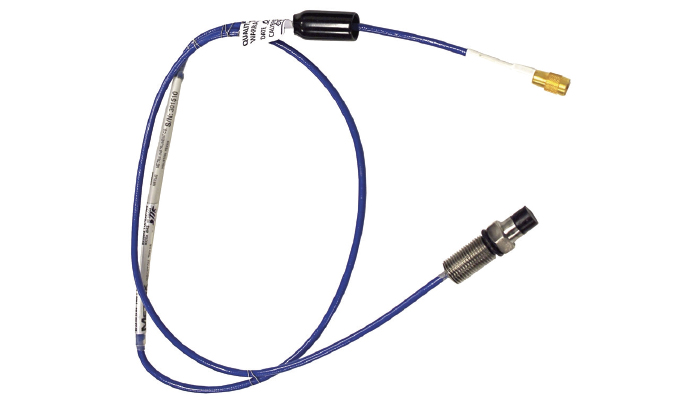
The proximity system generates eddy currents in the surface of the material. Depending on the range of the probe to the target material, the voltage output will be impacted by the eddy currents. The eddy currents generated in the target material are impacted by the material density, surface roughness and composition, and electromagnetic properties of the elements contained in the material.
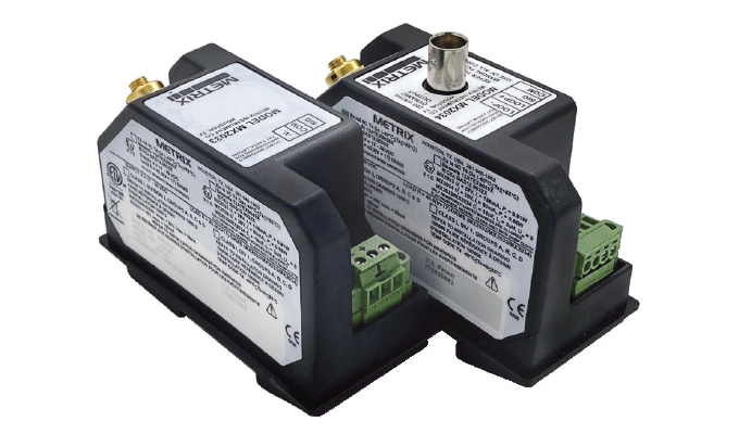
The DPS can accommodate differences in material, system length, and probe type. All of these materials below could have been ordered directly from the factory or custom calibrated in the field to be within the API 670 specifications of 200 mV/mil +/- 5 percent (7.87 mV/μm).
BENEFITS TO THE CUSTOMER OF THE METRIX DIGITAL PROXIMITY SYSTEM (DPS)
Once customers take the leap into digital proximity sensors, they generally find improved frequency and amplitude resolution and reduced need for spare parts inventories. Furthermore, given the DPS’s flexible nature, the system can be used with other manufacturers’ proximity probes and cables. Also, regardless of manufacturer, if the probe curves are outside API 670 specifications for linearity and incremental scale factor the DPS can be reconfigured to meet specifications. It can work in tight applications where normal probe clearances are not available.
FOR MORE INFORMATION
Metrix pioneered the concept of simple, affordable machinery protection with its mechanical vibration switch offerings, revolutionary 4-20mA vibration transmitters, robust high-temperature velocity sensors, and innovative impact transmitter technology for reciprocating machinery. Metrix has been ISO-9001 certified for more than two decades and is committed to quality and continuous improvement of its manufacturing processes. For more information, visit www.metrixvibration.com.
MODERN PUMPING TODAY, September 2022
Did you enjoy this article?
Subscribe to the FREE Digital Edition of Modern Pumping Today Magazine!