By Richard Smith and Chris Booth, AESSeal
See Part 1 Here
In last month’s beginning to this article, we posited that, although sealing devices account for only a small fraction of the energy consumed by pumps, significant energy conservation can be achieved by elegant sealing practices. In the conclusion that follows, we’ll more closely examine the ways energy content can be made lower in a modern context with mechanical seals by looking into real-world examples and case studies.
EVAPORATOR PUMPS CASE STUDY: CONVERSION FROM PLAN 32 TO PLAN 53
In this example, energy efficiency was improved by converting from a single mechanical seal with external flush (Plan 32) to a double seal with barrier system (Plan 53A). The application was at a scotch whiskey distillery where pot ale, a byproduct, is processed in a syrup evaporator to make animal feed.
Efficiency Loss Under API Plan 32
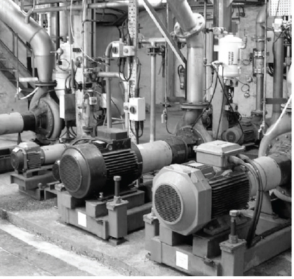
There are three evaporator circulation pumps, which were fitted with single mechanical seals and a simple Plan 32 flush (see figure 8). Clean fluid from an external source is used to flush the seal chamber, to exclude solids or contaminants, and to reduce the temperature at the seal. It is also used to reduce flashing or air intrusion (in vacuum services) across the seal faces. The main driver for the use of this system is its low initial cost.
A survey of the evaporator system revealed the inefficiency of this flush plan. Syrup was being fed to the evaporator at the rate of 40 gallons per minute, but also being diluted by 0.5 gallons per minute, per pump, of clean flush fluid. The additional 1.5 gallons per minute of liquid into the process meant having to evaporate at least 4 percent more liquid. An analogy is having to walk 26 miles to actually only cover 25.
In addition, the injected flush water came from a mountain stream source at 41 degrees Fahrenheit (5 degrees Celsius), so more heat was being added to the process to maintain evaporation temperature. Heating the cold flush water to the evaporation temperature requires 19 kilowatts, or 460 kilowatt-hours per day. Evaporating the flush water requires over 200 kilowatts or 4,800 kilowatt-hours per day.
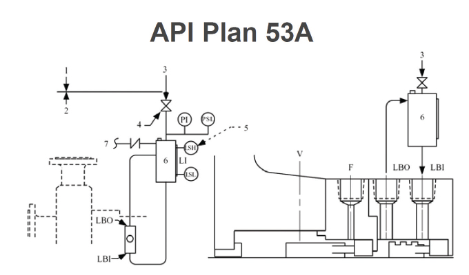
Conversion Efficiency Improvement Under API Plan 53A
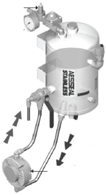
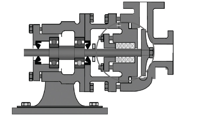
Conversion to a double seal system with Plan 53A (see figure 9) eliminated the need for seal flush. A small pressurized tank is introduced, containing 2.6 gallons (see figure 11) of barrier fluid. This is circulated either by convection or by a small circulating device built into the seal.
The pressurized barrier fluid provides a clean liquid environment for the inner seal faces and prevents air intrusion to the vacuum. With all three pumps converted (see figure 10), syrup production increased from 97 to 108 tons per hour resulting in a significant reduction in plant running hours. In addition, over 5,000 kilowatt-hours per day was liberated for better use elsewhere.
Evaporator Plant Installations
Any business operating pumps on evaporator systems needs to consider with great care the piping plan used on the pump seals. Plan 32 is often found in many industries, including pulp and paper, sugar production, and chemical process such as nylon manufacturing.
WATER QUENCH CASE STUDY: CONVERSION FROM QUENCH TO PLAN 53
A quench is similar to API Plan 62. Water from an external source is passed between two co-axial seals and away to drain. The water quench is used to prevent solids accumulating on the atmospheric side of the mechanical seal, and can considerably improve seal reliability.
Quench Usage and Effluent
This system (see figure 12) is common in many industries including brewing, distilling, pulp and paper, corn milling, sugar production, dairy processing, and chemical production.
Quench flow rates are typically just under a gallon per minute, per seal installation. In addition to the cost of the water used, the cost and energy consumption of effluent treatment should not be overlooked. The main driver for the use of this system is again its low initial cost
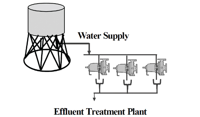
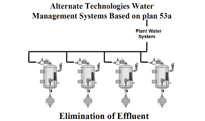
Thermosyphon Alternate Plan 53A Effluent Elimination
An alternative to this system is to use a barrier system (see figure 13), similar to API Plan 53A. Such systems are self-contained, and more importantly they produce no effluent. If the water supply is connected so as to both pressurize and maintain the level in the tank, no manual intervention is required, and maintenance costs are reduced. An air space can serve as an expansion volume, minimizing the effect of temperature changes. In the event of water supply interruption, the air volume and a check valve maintain pressure until supply is resumed.
BOILER FEED PUMP CASE STUDY: CONVERSION FROM GLAND PACKING TO MECHANICAL SEALS
This case study involves the conversion of a boiler feed pump from a traditional soft packing gland (see figure 14) to a Plan 23 mechanical seal. To help prevent the rubbing friction damaging the packing, the gland follower would be adjusted to allow a small leakage to flow, typically a slow drip rate. The leakage serves to assist in cooling and lubrication of the gland. As the packing and shaft wear, adjustment will be required to control the leakage rate.
The case study in question is for a boiler feed pump at a petrochemical facility in the northeast of the United Kingdom. The pumps were installed in the late 1970s and furnished with packed glands. The pumps are multi-stage units with glands at both drive and non-drive ends. This arrangement is typical of many applications around the world at chemical works and refineries. Most of the feed water pumps installed in this era were fitted with packed glands and many continue to run today using this technology. Leakage from the packed glands will be a pure loss to the operation.
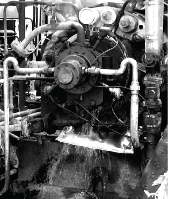
In this example the feed water in the pump was at 250 degrees Fahrenheit (121 degrees Celsius). Losses through the packed gland would need to be made up with water from the treatment plant. The calculation of the energy loss is based the energy required to take the make up water from 50 degrees Fahrenheit (10 degrees Celsius) to feed water temperature of 250 degrees Fahrenheit (121 degrees Celsius). In this instance the boiler plant is gas fired and the heat energy requirement can be translated into a net CO2 contribution. Due to a reduction in plant manning, the gland follower adjustment was only made when the leakage was severe. As a result, the average leakage rate from the pumps was about quarter gallon per minute per gland (see figure 15).
With eight pumps (sixteen glands) leaking on average a gallon every four minutes per gland energy loss is calculated at 124 kilowatts. The plant operates 24 hours per day, 365 days per year, giving an annual energy loss of 1,086,240 kilowatt-hours.
The energy savings are purely based on heating requirements and do not include energy costs for water treatment, de-aeration and any pumping. It is worth noting that the reduction in energy does not reduce the power absorbed by the pump but provides for savings in the combustion process and boiler operation costs.
Investigation of the combustion process by site personnel indicated that 4 ounces of CO2 is emitted per gallon of water heated. With losses of a quarter of a gallon per minute per gland (across sixteen glands), there is a calculated saving of 261 tons of CO2 pear year. By comparison the average European high efficiency diesel car covering over 12,000 miles per year would emit 3.5 tons per year; therefore, the saving is equivalent to nearly eighty cars.
MINERAL EXTRACTION SLURRY PUMP CASE STUDY: CONVERSION FROM GLAND PACKING TO MECHANICAL SEAL
Population growth, economic development, and climate change have led to pressure on the water supply in many parts of the world including the United Kingdom. According to the Organization for Economic Cooperation and Development (OECD), access to reliable and safe water represents one of the greatest challenges facing humanity in the twenty-first century. The use of flush water in pumping applications, sometimes in large quantities, must be questioned. This practice is still widespread around the world.
The final case study is the conversion to mechanical seals of a number of large slurry pumps with packed glands. The Debswana operation consists of various diamond mines at Orapa in Botswana, a dry semi-desert area. Essential to the operation are slurry pumps pumping kimberlite and iron silicate. These applications are amongst most abrasive in the slurry-pumping world.
Gland Water Requirement
The packed glands on the pumps needed flush water injection (Plan 32) into the process media, at a rate of 15 gallons per minute to exclude slurry from the seal chamber. If the water supply failed, damage occurred to the gland within thirty seconds. Only 10 percent of the flush water is recoverable from the process. A typical train of five pumps consumes over 35 million gallons per year of water from underground sources.
Due to constant extraction over many years, the water table was dropping and the resource was threatened. An official mandate was tabled to reduce water consumption by 10 percent immediately and 15 percent in the medium term. Pipelines from various alternative sources were considered. The most effective, and most extreme, was to build a 372-mile-long pipeline from the Okovango delta to Orapa at a cost of $30 million. This could have endangered water levels in the delta, a world heritage site.
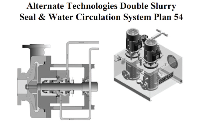
Double Seal Conversion
Fitting double seals with water circulation systems (see figure 16) to just eighteen pumps reduced gland water consumption by a significant proportion of the 10 percent total savings required across the site. A further fifty seals and systems have now been installed, covering all the pumps using large volumes of gland service water.
Energy Saving
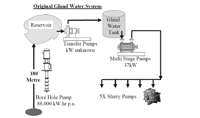
The primary motivation for the conversion was to tackle the issue of aquifer depletion; however, the secondary benefit of energy conservation should not be overlooked. The complete original gland water system needs to be considered. The system illustrated at Damtshaa mine (part of the Debswana operation) is typical of many of the mines in Orapa (see figure 17). Energy saving are made because bore hole pumps are no longer required to lift the volume of gland water to a storage reservoir on the surface.
Typically, a bore hole is drilled to over 800 feet with the water table at approximately just under 600 feet. Bore hole pumps are of the helical rotor type and being belt driven are approximately 75 percent efficient. From the reservoir, a multistage pump increases pressure injecting the gland water into the pump casing. The calculated energy consumption of this system is 394,084 kilowatt-hours per year. African power generation is highly dependent on coal. For every kilowatt saving, there is an equivalent atmospheric saving of over 2 pounds of CO2. The double seal conversion utilized a simple tank recirculation system, with total energy consumption of less than 30,000 kilowatt-hours per year. Hence, energy savings of over 350,000 kilowatt-hours per year were achieved.
CONCLUSIONS
Consideration of pump seal auxiliary piping systems needs to be given greater priority. The energy indirectly consumed is often ignored, with minimum capital cost being the prime driver when plants are designed. In addition, mature pump installations fitted with traditional high maintenance packing arrangements should be reviewed in terms of plant efficiency. The mechanical seal industry has developed efficient, elegant solutions that provide the operator with higher reliability, lower life-cycle costs, and reduced environmental impact.
FOR MORE INFORMATION
AESSeal is a specialist in the design and manufacture of mechanical seals and support systems. AESSeal’s mechanical seals are used in a wide range of pumps and rotating equipment worldwide to prevent liquids and gases escaping into the environment. AESSeal manufactures mechanical seal types to suit all industries and its investment in modular design means that the company provide the best on-time delivery performance in the industry. The AESSeal range of seals, seal support systems, and bearing protectors are all designed to improve pump reliability and reduce maintenance costs. For more information, visit www.aesseal.com.
MODERN PUMPING TODAY, November 2021
Did you enjoy this article?
Subscribe to the FREE Digital Edition of Modern Pumping Today Magazine!