By Richard Smith and Chris Booth, AESSeal
Sealing devices account for only a small fraction of the energy consumed by pumps. The scope for energy conservation at first appears limited; however, this following article details areas where significant energy conservation has been achieved by elegant sealing practices. Process industries have enjoyed savings in energy associated with seal cooling water circulation. A correlation between effluent reduction and carbon emission is postulated. Technology can provide the process industries with significant efficiency improvement in seal cooling. Case studies are reviewed from several industry sectors. API standards endorse many of these techniques as best practice. The mechanical seal industry contribution is key in assisting pump users to play their part in reducing adverse climate change.
HOW TO MAKE A DIFFERENCE
Pumping of liquids in the service and process industries is a significant user of energy and, consequently, a major contributor to CO2 emissions. The link between rising atmospheric CO2 (see figure 1) and climate change has been fiercely debated, but now appears to be generally accepted by mainstream science. Industry leaders have committed their corporations to developing technologies that will help reduce carbon emissions. Such actions may be visionary or recognition of a significant market opportunity, or both. The reader is left to decide.
Can the pumping community (users, manufacturers, and component suppliers) make a difference to carbon emission levels? In the United Kingdom, electric motors account for 40 percent of total electricity consumption. Pumping equipment is estimated at 32 percent of this, or 13 percent of total electricity demand. If the United Kingdom is typical of modern developed economies, then improvements in pumping efficiency can have a significant impact on carbon emissions. Can the pumping community rise to this global challenge?
ENERGY SAVING AND MECHANICAL SEALS
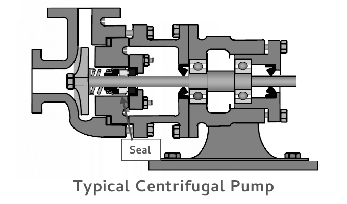
Most pumps require a sealing device to prevent liquid escaping from where the drive shaft enters the pump casing (see figure 2). In the developed world, mechanical seals have replaced traditional gland packing on the majority of newly installed industrial pumps. With many mature pump assets still in use the potential remains for reductions in energy consumption by replacement of gland packing.
Where mechanical seals are fitted, seal frictional losses account for as little as 1 percent of total pump power consumption, hence the potential energy savings from improved seal technology are low. However, experience shows that much larger energy efficiency improvements can often be made by improvements to the seal support system.
ENERGY SAVINGS FROM SEAL SUPPORT SYSTEMS
Mechanical seals in process industries are often reliant upon supporting auxiliary fluid systems. Referred to as “piping plans” or “seal support systems,” these improve the operating environment of the seal to provide reliable operation and longer seal life. The energy consumed indirectly by the seal support system is often overlooked, but can be considerable.
The American Petroleum Institute (API) in its international seal standard API 682 (ISO 21049) recognizes twenty-six piping plans; many other variations are also used. These generally fall into two main groups:
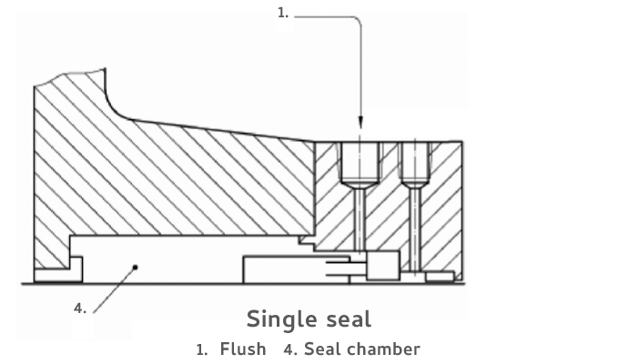
- Flush: Clean, cool liquid is injected into the seal chamber to improve the operating environment (see figure 3a).
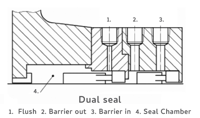
- Barrier or buffer: A secondary fluid is fed to the space between two co-axial mechanical seals to prevent atmospheric contact with the pumped fluid, improve seal cooling, or enhance safety (see figure 3b).
With hot processes, a flush system injects cool liquid into the process stream, which must in turn be heated to compensate. Barrier systems remove heat from the process, then cool the secondary fluid before returning it to the seal. If the flush or barrier were not present, the process would require less energy. Heat exchangers are often used to cool the flush or barrier fluid, requiring a supply of pumped cooling water or a fan to drive air past the vanes of the exchanger.
A smart approach to seal support systems can improve energy efficiency and provide significant reduction in energy costs and carbon footprint.
BOILER CIRCULATION PUMPS: CONVERSION FROM API PLAN 21 TO PLAN 23
This first example illustrates the efficiency difference between two (process side) flush piping plans. Single seals operating in higher temperature media often require additional cooling. This may be needed to improve the margin to vapor formation, to meet secondary sealing element (e.g., O rings) temperature limits, or to reduce coking or polymerization.
There are two piping plans commonly used in industry, referred to here as API Plan 21 and API Plan 23.
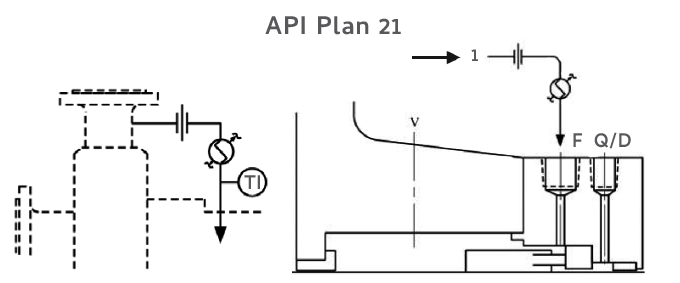
In API Plan 21 (see figure 4), process fluid is circulated from the discharge of the pump, through a restriction orifice and a cooler, then into the seal chamber. The cooler is removing heat from the process stream, reducing overall process energy efficiency.
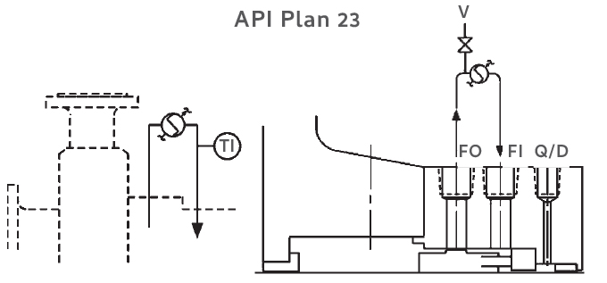
In API Plan 23 (see figure 5) is a more efficient way to provide cooling for the mechanical seal. Liquid is recirculated from the seal chamber, through a cooler, then back to the seal chamber. Circulation is driven by a rotating pumping ring in the seal chamber, which may be integrated with the mechanical seal. Instead of constantly cooling a part of the process stream, only the contents of the seal chamber are cooled. This minimizes the load on the cooler, since the heat to be removed is only the heat generated by the seal faces plus the heat soak through the seal chamber casing.
PLAN 23 BOILER FEED PUMP APPLICATION
Energy Saving
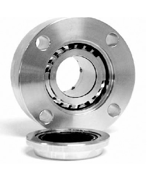
One such application was the boiler water feed pumps on a modern CHP plant supply at a paper recycling mill. Operating at 320 degrees Fahrenheit (160 degrees Celsius), and seal chamber pressure 8 bar(g), this application serves to illustrate the difference between the two plans. The pumps were fitted with a traditional seal of 85mm diameter cooled by API Plan 21 configuration. Service life of the seals was less than twelve months, with associated problems of cooler fouling. A software package developed between the cooler manufacturer and AESSeal was used to calculate cooler heat loads for both Plan 21 and Plan 23 operation. Plan 21 results demonstrated that the seal would be operating at seal chamber temperatures of 226 degrees Fahrenheit (108 degrees Celsius) and with cooler heat load in excess of 14 kW. Using the same basic operating parameters, an SMSS 23 (see figures 6 and 7) mechanical seal on Plan 23 operation gave significant efficiency improvement. Seal chamber temperature drops to 116 degrees Fahrenheit (47 degrees Celsius), with the cooler heat load falling to 1.9 kW almost 1/8th of the heat load of the Plan 21 system. The reduction in cooler load does not reduce the power absorbed by the pump but provides for two potential savings. First, almost 12kW less heat is required to operate the boiler. Second, reduced load on the cooling water waste-heat removal system results in lower maintenance costs.
Reliability Improvement
A similar exercise was undertaken on a ship application, which demonstrated similar reduction in cooler load. Mean time between failure of the original Plan 21 arrangement was less than twelve months with cooler fouling being the root cause of failure. The SMSS Plan 23 conversion has now been operating since 2002 with no failures to date.
Industry Adoption
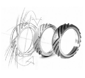
Industry adoption of the preferred and more efficient Plan 23 is currently low. Plan 21 is far more popular. This is because traditionally Plan 23 seals were expensive due to the cost of including the pumping ring and complex tangential porting in the seal chamber. Modern machine tool techniques combined with innovative modular cartridge designs (see figure 6) have made the implementation of such seals easier on both new and retrofit pumps. Cost has been reduced by fully integrating the pumping ring and ports into the seal cartridge. Development of efficient bi-directional pumping rings (see figure 7) serve further to simplify installation on between bearing multi-stage machines.
In a recent proposed design of a petrochemical facility to be built in the Middle East, 10 percent of the applications were originally specified as Plan 21. After demonstrating the energy savings to be made, these were changed to Plan 23. It is still common to find a high incidence of Plan 21 on major projects where capital cost has been the over-riding factor, such as combined heat and power (CHP) plants.
BEST PRACTICE
API 682 offers an excellent tutorial on the reliability improvements that can be obtained with Plan 23 and states that Plan 23:
- is the plan of choice for all hot water services, particularly boiler feed water,
- is also desirable in many hydrocarbon services where it is necessary to cool the fluid to establish the required margin between fluid vapor pressure and seal chamber pressure.
This duty is usually much less than that in a Plan 21. Lessening the duty is very desirable because it extends the life of the cooler. The industry has considerable negative experience with Plan 21 because of cooler plugging.
— API 682 3rd Edition ISO 21049
A LOOK AHEAD
In next month’s conclusion, we’ll more closely examine the impact sewage treatment has on energy consumption as well as the ways its energy content can be made lower in a modern context with mechanical seals. Whether it be the complex treatment of industrial effluent or the more direct treatment of wastewater and small processing plants, energy savings and environmental benefits are both possible and applicable.
FOR MORE INFORMATION
AESSeal is a specialist in the design and manufacture of mechanical seals and support systems. AESSeal’s mechanical seals are used in a wide range of pumps and rotating equipment worldwide to prevent liquids and gases escaping into the environment. AESSeal manufactures mechanical seal types to suit all industries and its investment in modular design means that the company provide the best on-time delivery performance in the industry. The AESSeal range of seals, seal support systems, and bearing protectors are all designed to improve pump reliability and reduce maintenance costs. For more information, visit www.aesseal.com.
MODERN PUMPING TODAY, October 2021
Did you enjoy this article?
Subscribe to the FREE Digital Edition of Modern Pumping Today Magazine!