By Walt Prentice, Applied Flow Technology
No longer is over-engineering, or designing from heuristics, as necessary as it once was. Why? Because engineers can build and test systems in a computer rather than in the field. Flow analysis software has improved multiple facets of hydraulic system engineering. As technology improves, knowledge expands, and communication systems tighten, engineering teams can better prepare for unexpected events, design for the most efficient systems, and leave clearer footprints behind for future engineers to follow.
UNEXPECTED EVENTS
Things rarely go exactly as planned: in pumping systems and in life. At some point, an emergency shutdown or power failure will impact the system. In the past, the safe approach was to over-engineer the system to mitigate any perceived worst-case scenarios. However, the introduction of modeling software allows widespread testing of these scenarios to predict system responses without having to test in the field, or worse, to find out during the event itself. Yet, over-engineering is still common today. While better tools exist, it takes time for them to take root and become standardized. Two main reasons software modeling is advantageous are:
- The assumed worst-case scenarios often do not account for everything.
- Over-engineering leads to waste.
A common worst-case scenario is a waterhammer event and the resulting pressure surge. The failure of traditional methods for predicting waterhammer repercussions come from a lack of understanding the methods’ limitations. Engineers must identify the maximum pressure that could arise in a piping system to ensure safety and meet code. Typically, that involves a few extreme assumptions, such as an instantaneous valve closure, and applying pressure-rise calculations. Yet there are three common situations that escape the engineer’s view: line pack, wave reflections, and liquid column separation.
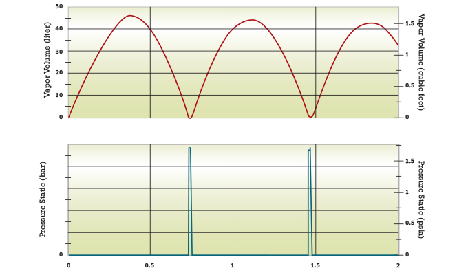
Figure 1 demonstrates how liquid column separation causes pressure spikes downstream of a fast valve closure. The initial pressure rise occurs on the upstream side from sudden flow stoppage, but the downstream side sees low pressure, causing vapor formation, leading to other pressure surges from vapor pocket collapse. Traditional analyses do not predict this and can leave the engineer with incorrect expectations.
The other problem with traditional approaches is waste. If systems are designed with unrealistically bad expectations, more money and resources are spent than necessary. This leads to higher costs, lower efficiency, and more complicated systems. Engineers should always design for the simplicist, most effective solution, which is best determined through modeling.
EFFICIENCY AND COSTS
Current design is driven by the best and most cost-effective solution, not only one that gets the job done. Fluid modeling has improved both pump and system efficiency. For example, engineers can digitally build their system to determine what head rises are required for various flow rates and conditions. Then they can look at capital and operating costs to see what pump configuration is best suited.
One example of efficient software design was a refinery cooling loop redesign. It had four pumps in parallel as standard operation. One of them vibrated violently and eventually failed. After years of operational changes, no one had hydraulic models to see the effects until consultants were called to help. Modeling software revealed the problematic pump ran far outside its preferred operating region and that two pumps in parallel were more cost effective than four. Not only were operating costs reduced, but the remaining pumps would be running at their best efficiency point (BEP), as shown in figure 2.
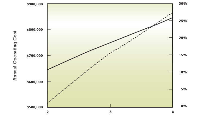
This is not initially obvious because spreading the load across four pumps sounds less stressful than loading two. However, pumps are built to operate in certain regions, and factors like these must be considered during design. Without software, these efficiency sweet spots in complicated systems are much harder to identify. The study both extended pump life and saved $200,000 a year simply by modeling the system.
Similar thinking can be applied to pipe sizing, as there are both capital and operating costs to consider. Smaller pipes generally cost less, but they cause more frictional losses. This means the pump needs to supply more pressure than it would in larger pipes to drive the same flow. Hypothetically, though a pump may be sized “properly” according to the system proposal, that system may have been sized inappropriately, resulting in the owner spending more money than necessary.
Considering all the factors that go into system sizing is overwhelming. It is impossible to view all the possibilities and choose the right one. This leaves engineers to size by heuristics or company standards. These days there is a much simpler, more effective way, and that is to plug all the design information into a computer, and let it do the heavy lifting. The result is a better system, if not the optimal, for both the designers and owners.
MOVING BEYOND SPREADSHEETS
Unfortunately, it is common for engineers to inherit spreadsheets or incomplete system drawings. Projects and ownership change over time, and these kinds of documents are rarely updated. Engineers then spend way too much time deciphering and fixing, rather than focusing on the main task. Models improve the accessibility of the next engineers to do their analyses.
The practical benefits of having a prebuilt model are apparent. When an unexpected problem arises, the engineer can easily make changes and run tests to determine the cause. When repairs or replacements are needed, the engineer can model the effects of changing flow paths to see the effect on operation. When the owner needs an expansion, the engineer can model it for optimization. Any software learning curve is much easier to overcome than trying to comprehend incomprehensible documents and calculations.
Today’s engineers have more standards, specializations, and tools than any generation before. Hydraulic modeling software is one tool that helps engineers accurately prepare for unexpected events, steer pump and system efficiency, and give future engineers better access to analysis. It is a bold step forward, but the benefits far outweigh any hesitation.
FOR MORE INFORMATION
Walt Prentice is a business applications engineer at Applied Flow Technology (AFT). Prentice holds a bachelor of science in chemical engineering with a minor in economics from the Colorado School of Mines. At AFT, he supports engineers around the world to troubleshoot their piping and ducting models. For more information, visit www.aft.com.
MODERN PUMPING TODAY, July 2021
Did you enjoy this article?
Subscribe to the FREE Digital Edition of Modern Pumping Today Magazine!