In part one, the normal and excessive leakage rates of mechanical seals were discussed based on the monitoring function of API piping plan 76. Part two focuses on common causes, possible remedies and seal design features to mitigate typical seal face damages in NGL services. It is generally accepted that the mechanical seal is the most sensitive component in a pump and usually drives the need for maintenance and repairs. This is especially true in the NGL pipeline industry due to challenging operating conditions in combination with poor lubricating characteristics of typical NGL fluids.
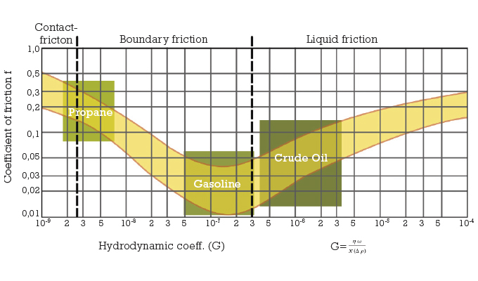
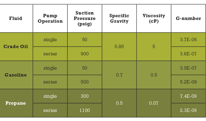
Figure 1: Lubrication diagram of mechanical seals
SEAL DUTY LEVEL OF TYPICAL PIPELINE SERVICES
To get a better understanding of the degree of difficulty of an application with respect to friction, wear, and leakage, it is useful to compare three different pipeline applications handling a light crude oil, a refined fluid such as gasoline and a light flashing fluid such as propane. Figure 1 shows an f-G plot for mechanical seal faces in general, i.e. regardless of OEM or seal type. Whereas f is the overall coefficient of friction, G is a hydrodynamic coefficient that characterizes the lubrication regime for a set of simple flat seal faces under a given set of conditions, i.e. viscosity of the fluid, seal face sliding velocity, pressure differential, and the force balance ratio of the seal face. Mechanical seals operate within three lubrication modes: (1) dry contact friction without any fluid film support, (2) boundary friction or mixed lubrication, i.e. part mechanical contact and fluid film load support, and (3) liquid friction or full fluid film lubrication, i.e. no face contact. The table summarizes the operating conditions for a 4-inch shaft diameter turning at 3600 rpm.
The diagram illustrates that from a frictional perspective, the seal faces in the crude oil application will tend to separate and operate on a thin fluid film due to hydrodynamic effects in the seal face gap. There will be some visible leakage with very little to no wear of the materials. The gasoline seals will operate with slight contact but wear and leakage will still be minimal. The propane seals on the other hand, will operate with strong contact friction, especially in the second or third pump when pumping in series, and will wear out quickly and will be sensitive to face damages. Other common NGLs such as Y-grades (variable compositions of ethane, propane, pentane and butane), ethane-propane mixtures, and pure ethane will all operate in the region of the propane case example or worse. In the region of high contact, special features in the faces will be necessary to enhance face lubrication to extend the lifetime of the seal. As compared to gasoline and crude oil, NGL fluids will vaporize in the seal face gap. This is the result of the pressure drop across the seal faces and the face temperature rise due to friction. This additional complication must be dealt with through specific features in the seal design and adequate seal chamber pressure and flush flow rate in the piping plan for the primary seal.
Other challenges of pipeline services involve the operation of the pumps and pipeline, i.e. variable product demand, intermittent operation, variable speeds, occasional presence of solids, limited accessibility for personnel, no utilities, and single or series/parallel pump operation. All these characteristics result in a very tough demand for the mechanical seals.
TYPICAL SYMPTOMS OF FAILED SEAL FACES AND THEIR POSSIBLE CAUSES
Figure 2 shows failed seal faces, which operated for several months in a Y-grade pump with a suction pressure of approximately 750 psig. The seal design is dual unpressurized, contains rotating springs and is similar to a typical API682 standardized seal but beefed up for the higher pressures in the pipeline.
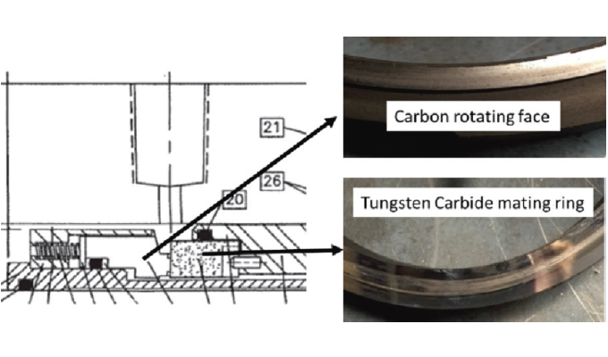
Figure 2: Typical symptoms of failed seals in NGL service
The symptoms are very typical for many failed NGL seals: severely worn carbon graphite seal face, i.e. the seal face had lubrication grooves but the wear rate was so high that the grooves disappeared. The face was also chipped at the edges of the rubbing or contact area. The tungsten carbide mating ring exhibited a deep wear track with phonographic grooving and thermal cracks. The possible causes for such damages are numerous:
- Installation errors
- Hang up of the dynamic o-ring
- Insufficient flush flow
- Inadequate vapor pressure margin
- Too much distortion of the seal faces
- Shaft shuttling in axial direction
- Solids in the flush fluid
The bottom line is that in many failure cases, the observed part symptoms can be the result of a variety of reasons and usually requires a process of elimination to determine the most probable cause(s). DCS data from the pump and plan 76 backpressure tends to be helpful in the failure analysis process. In this specific case, it was simply that the seal was too weak for the duty. Seal faces deform under the influence of pressure and temperature. When the net deformation becomes excessively “A” or concave shaped as shown in figure 3, the fluid will vaporize immediately as it enters the gap and cause very high, erratic friction as all load support of the fluid film is lost. In other words, the contact force and resulting friction become so high that damage to the seal faces is inevitable, resulting in erratic leakage behavior that causes pressure spikes in the plan 76 and eventually will shut down the pump.
Figure 3: Typical pressure deformation of seal faces
COMBATTING FACE DEFORMATIONS
As the seal faces are typically exposed to a range of operating conditions and fluids, it is imperative to minimize seal face distortions through design and material optimizations. The more fluids are transported through the same pipeline, the more challenging this task becomes. Each new load condition will affect the shape of the seal face gap and alter frictional heat and leakage.
Figure 4 shows a standardized, high-pressure seal for NGL pipeline service of which the seal faces are calculated and designed with customized software that predicts the friction-leakage behavior for a wide range of NGL and refined fluids under minimum and maximum pipeline operating conditions. In addition, their dynamic performance is checked on a laboratory test rig to validate the analytical predictions.
Whereas the failed seal in figure 3 contains rotating springs and hard-soft face materials, the high-pressure pipeline seal features stationary springs, and hard/semi-hard face materials. The material properties are critical to minimize deformations. Table 1 shows a comparison of the most commonly used carbon graphite material versus a semi-hard material, which consists of silicon carbide and carbon. The strength as well as thermal properties are far superior for the compound material, which results in improved seal face gap stability under variable operating conditions. The compound material also has proven to be more forgiving to the occasional presence of solids in the fluid stream.
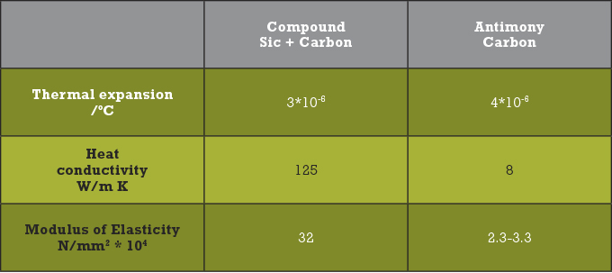
Table 1: Face Material Comparison
AVOIDING INFANT MORTALITY FAILURES AND CATASTROPHIC NGL RELEASES
The stationary spring orientation offers several important advantages when dealing with difficult applications such as NGL pipeline services. In general, stationary spring seals are preferred for large shaft diameters and higher speeds because they are far more forgiving to alignment related issues between the interface of the pump case or seal chamber and seal flange. Consequently, the potential for infant mortality type failures due to poor installation of the seals is greatly reduced. Stationary spring seals also offer the advantage of very stiff seal face shapes, encased with metal shrouds to prevent complete loss of sealing functionality if one or both seal faces would fracture and shatter apart. The latter breakdown of a seal is the worst possible scenario as it results in a significant safety and environmental hazard but can be avoided by protecting the seal faces in case an unintended upset or equipment malfunction would occur.
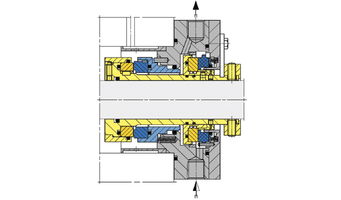
Figure 4: Standardized pipeline seal type SHI300
LEAKAGE CONTAINMENT AND SAFETY
The vast majority of NGL seals are dual unpressurized and incorporate a low pressure, rotating spring type, non-contacting, or contacting containment mechanical seal. The maximum pressure rating of these containment seals varies from 200 to 600 psig, which is well below the maximum pipeline pressure of 1440 psig. This may present a safety hazard in especially the second or third pump in series operation. It is safer to use a stationary spring non-contacting containment seal such as shown in figure 4, which is rated for full pipeline pressure and provides the installation related benefits.
DRY GAS SEALS FOR NGL PIPELINE SERVICES
In the operating area of NGL seals in the lubrication diagram (see figure 1), Dry Gas Seals have also proven to be very reliable while operating with low leakage rates. Whereas well operating, contacting wet lubricated seals operate with low contact forces, dry gas seals operate on a thin gas film with no contact. Figure 5 shows a standardized DGS seal equipped with DiamondFaceTM technology, specifically developed for pump NGL applications. The seal faces are fabricated in silicon carbide, coated with crystalline diamond. From a stiffness perspective, it is the best possible solution due to the high strength and thermal conductivity of the base material.
The addition of diamond offers several advantages due to its great physical properties: temporary contact can be tolerated, best wear resistance in case of contact, conducts heat very well, which allows for operation with very thin films. The film thickness is critical to vaporize the fluid before or as soon as the fluid enters the sealing gap. The thinner the film, the more heat is generated, hence the faster the fluid will flash to a gas. Another benefit of the thin film is low leakage. Experience indicates that DF-DGS seals can operate with low, i.e. 0 psig and high vapor pressure margins, i.e. in excess of 500 psig. A last important benefit of Dry Gas Seals is that the required flush flow rates are very low as compared to wet lubricated seals. Whereas wet lubricated seals typically require flush flow rates of 10 to 20 gallons per minute per seal, a DGS seal can operate with no flush at all if the fluid is free of solids. If solids are present, a filtering system (API plan 12) is recommended but a flow rate of 1 gallon per minute will be sufficient for proper operation. This major reduction may have a significant impact on the flow through the pump and/or pipeline.
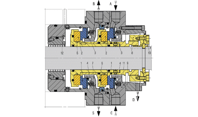
Figure 5: Dry Gas Seal type DF-DGS6
VIEW AHEAD
Recent incident reports and studies of pipeline equipment indicate that pump seal performance is likely at the root of a significant increase in releases to the environment. Although these releases are small compared to a breach in a pipeline, they are of great concern to pipeline companies. While crude oil and refined fluid pipelines have been around for a long time, the pumping of NGLs is relatively new and presents demanding challenges for the mechanical seal and pump OEM’s. Increasing energy demands will require larger pumps, higher pressures, speeds and fluids. API 682, the governing mechanical seal standard for mechanical seals in hydrocarbon services, is a great foundation for the sealing of process plant equipment but falls short for main pipeline services. Not only because of the more demanding operating conditions, but also because of the different operating character of the pumps in a pipeline. Therefore, the next edition of the API682 standard (5th) may include more specifics on the design aspects and selection of seals and piping plans for pipeline pumps.
ABOUT THE AUTHOR
Eric Vanhie provides senior expert technical sales support for EagleBurgmann Industries. EagleBurgmann operates manufacturing, engineering, testing, and administrative functions at its Houston headquarters including a dynamic dry gas seal test facility. EagleBurgmann USA employs 220 people in six service center locations throughout the country. With a pronounced understanding for quality and service as well as customer orientation, they draw on their knowledge and expertise to provide local support to customers and solve problems quickly and efficiently. For more information, visit www.eagleburgmann.us.
_______________________________________________________
MODERN PUMPING TODAY, November 2018
Did you enjoy this article?
Subscribe to the FREE Digital Edition of Modern Pumping Today Magazine!