Figure 1: Dual unpressurized seal with API plan 76
This article addresses the normal and excessive leakage rates of mechanical seals in main pipeline pumps that transport Natural Gas Liquids such as ethane, propane, butane and various mixtures of these liquids. In some pipelines, these liquids are pumped in batches ranging from very light, flashing liquids to heavier, non-flashing liquids such as gasoline products. The wide span of fluid properties combined with variable pressures and speeds present difficult challenges for the mechanical seals. From a mechanical seal face lubrication perspective, NGL’s are poor lubricants due to low viscosity, density, and high or low vapor pressure.
Practically, it means that the potential for minor or major face damages is high and the resulting emissions into the environment can be significant if not timely contained. In addition, excessive leakage will eventually force the operator to shut down the pump, which may result in production loss and high equipment maintenance costs. In industrial plants such as refineries and petro-chemical plants, end users have detailed expectations of emissions from pumps, agitators, valves, and flange connectors because the EPA regulates them (see reference 1). This is not the case for pipeline pumps.
TYPICAL MECHANICAL SEAL AND API CONTAINMENT PIPING PLAN FOR NGL PUMPS
Figure 1 shows the typical containment-piping plan (API plan 76) for flashing hydrocarbons. It is used with arrangement 2 seals (dual unpressurized seals) to route, dispose and monitor the mechanical seal face leakage of the primary seal (QL). In a process plant, the containment seal may be connected to an external nitrogen gas purge (API plan 72) to minimize emissions to the environment and avoid explosion/fire hazards arising from the leakage of the primary seal (QL). The gaseous NGL leakage of the primary seal (QG) and a small amount of nitrogen flow to a flare or vapor recovery system for disposal.
In a typical pipeline station, nitrogen and a vapor recovery system are not available. Consequently, the leakage escapes into the surrounding environment. Pipeline operators monitor the primary seal leakage via the pressure measurement with a pressure transmitter/indicator. The system includes a 1/8-inch orifice to induce backpressure as a function of the actual leakage rate of the primary seal.
The end user and/or pump supplier should be vigilant and work with the seal supplier to define the normal and maximum leakage rates for all the possible fluids and operating conditions that the seal may be exposed to and then evaluate the setup of the containment system for alarm and pump shutdown points through the DCS system. Table 1 shows the calculation results of the orifice backpressure in the plan 76. Three common NGL liquids were calculated for illustrative purpose. The average of the three cases shows that a substantial amount of fugitive emissions end up in the environment if a slight backpressure is created due to excessive leakage of the primary seal.
Typically, the alarm and/or pump shut down points are set at 10 psig or higher which means that operating mechanical seals with low or elevated backpressures results in significant product loss as well as very high emissions into the environment. The reason for these high set points is to avoid frequent “nuisance” alarms and/or pump shutdowns. As compared to the current emission limits in process plants (500 parts per million as measured by EPA method 21), the fugitive emissions at 1 psig backpressure in a pipeline pump would be in the order of magnitude of several hundred thousand PPM (see reference 1).
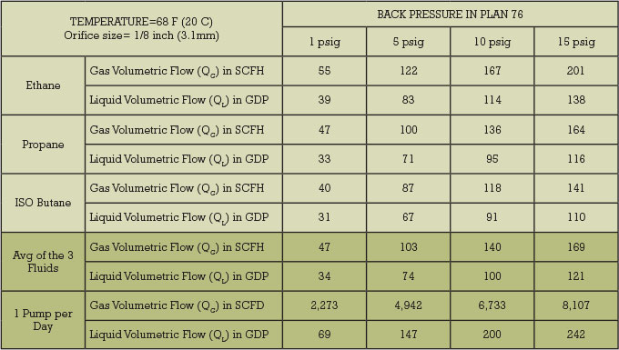
Table 1: Orifice calculation of plan 76 where SCFH = standard cubic feet per hour and GPD = gallons per day
DETERMINING THE LEAK RATE
“How much should this seal leak? How much can this seal leak before it becomes a problem? The seal is leaking. Should I remove it from service?” These are questions posed to mechanical seal manufacturers every day. Unfortunately, the answers can be complex and often lead to questions that are even more difficult (see reference 2). The main variables that determine the leak rate of a seal are the seal face gap height or film thickness, the viscosity of the liquid in the sealing gap, the pressure differential, and face sliding velocity. Most important is the cubical relationship between the leak rate and gap height, meaning that small changes in the gap height or shape will have a significant impact on the leak rate. Cyclic operating conditions will alter the flatness of the seal faces and change the gap height or film thickness with each new operation condition. The amount of distortion and rate of change can have a detrimental impact on sealing performance, reliability, and lifetime if not adequately optimized through design and lab testing.
Consequently, stiff seal face designs and strong and thermal conductive materials are imperative to maintain low leakage rates while minimizing the potential for face damages. Any damages, even slight, will increase the leakage rate significantly because of the low viscosity of the fluids combined with relatively high-pressure differentials. Specifically, poor lubricating conditions will lead to vaporization of the fluid film; causing seal face wear, phonographic grooving, chipping of the materials and thermal cracks that can trigger alarms in the containment system of the mechanical seal or in worst case shut down the pump. The latter scenario occurs often in NGL pipeline pump seals.
Although the operating principles are similar for all mechanical seals, i.e. regardless of the manufacturer, leakage rates can be significantly different depending on proprietary face technology, design of the mechanical seal and materials. In applications involving fluids with poor lubricating qualities, it is quite common to enhance lubrication by adding specific features to one of the seal faces, i.e. lubrication grooves. These lubrication enhancement features will be different between seal suppliers and therefore may have different leakage rates.
The minimum, normal, and maximum leakage rates for the three NGL’s at ambient temperature, at typical min and max suction pressures will range between 50 mL/hr (approximately 0.3 gallons per day for isobutene at 200 psig) and 3000 mL/hr (approximately 20 gallons per day for ethane at 1000 psig). The corresponding backpressures in the plan 76 for these leakage rates equate to 0 psig and 0.25 psig respectively. In other words, a well operating seal should show for most of the typical NGL fluids 0 psig backpressure. Operating mechanical seals with backpressures of 1 psig or higher implies damages or excessive wear of the seal faces or an o-ring that is leaking. This does not mean that the seal cannot continue to operate, but can be at the expense of a substantial environmental impact and substantial product losses.
A LOOK AHEAD
In this respect, it may be interesting to look back in the past when the process industries started to implement programs to meet stringent emission limits. Pumps with high emissions were also identified as “bad actors” with respect to equipment reliability (see reference 3). Fixing the emission problem not only improved the sealing performance but also the mean time between repair of the seals, thereby reducing the life cycle cost of the equipment considerably. In a second article, possible remedies will be discussed to mitigate the typical seal face damages in NGL pipeline services.
REFERENCES
“Protocol for Equipment Leak Estimates,” EPA-453/R-93-026 (June 1993).
“A Contemporary Guide to Mechanical Seal Leakage,” John Merrill, EagleBurgmann, Texas A&M University, Turbomachinery Laboratories (2009).
“Meeting Emission Legislation Requirements with Today’s Advanced Technology Mechanical Seal Systems,” European Sealing Association publication 005/95.
FORE MORE INFORMATION
Eric Vanhie provides senior expert technical sales support for EagleBurgmann Industries. EagleBurgmann operates manufacturing, engineering, testing, and administrative functions at its Houston headquarters including a dynamic dry gas seal test facility. EagleBurgmann USA employs 220 people in six service center locations throughout the country. With a pronounced understanding for quality and service as well as customer orientation, they draw on their knowledge and expertise to provide local support to customers and solve problems quickly and efficiently. For more information, visit www.eagleburgmann.us.
_______________________________________________________
MODERN PUMPING TODAY, October 2018
Did you enjoy this article?
Subscribe to the FREE Digital Edition of Modern Pumping Today Magazine!