Cooling towers are increasingly being used to provide cooling water to power plants, and in last month’s introduction we looked at some of the common problems at cooling tower intakes. This month, we begin our examination of how, based on several hydraulic model studies, plant operators can best overcome potentially adverse flow patterns that may not directly impact the pumps but have a negative impact on the operation of the station.
CONVEYANCE OF FLOW FROM THE COOLING TOWER BASIN TO THE PUMP INTAKE STRUCTURE
When designing an intake structure from a cooling tower special consideration should be given to the area in which flow is transferred from the cooling tower to the pump intake fore-bay. Typically, the cooling tower basin and the pump intake floors are at different elevations with the cooling basin higher. This presents a problem area in which the conveyance of flow must be given careful consideration. The flow entering the intake structure from a higher basin floor will generally result in higher velocities close to the water surface in the pump fore-bay, which could extend to the pump bays contributing to vortex activity. Thus, the transition from the basin floor to pump intake floor presents a critical design challenge where consideration needs to be given to the size of the fore-bay, the extent of the floor elevation drop, size of any gate openings, and the distance from the basin to the pumps.
The flow entering the pump intake fore-bay from the cooling tower basin could be jetting from the cooling tower gates, or cascading into the intake structure from one or more sudden drops in floor elevations. The jetting flow can entrain air as well as restrict flow into the fore-bay of the structure. If the jet is strong enough it may cause supercritical flow regions. In the case of a sudden drop in floor elevation or cascading flow with a number of drops, the resulting free over-fall into the intake may cause problems. If the water level in the basin is not high enough, the critical depth at the brink of the drop may be lower than that needed for sufficient inflow to pumps, thereby starving the pumps. Also, the turbulence entrains air into the system. The gate that divides the cooling tower and fore-bay should also be in the designers’ mind at this point, and has a big impact on the flow conditions entering the fore-bay. In general, a smaller sized gate will have a greater chance of creating objectionable flow patterns, where as a large opening would reduce the velocities entering the fore-bay and result in fewer objectionable flow patterns. Due to space limitations, sloping floors to accomplish the change in elevation may be too steep, resulting in supercritical flow and associated problems such as formation of a hydraulic jump.
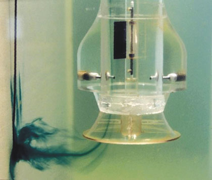
Figure 1: Detrimental Subsurface Vortex
FORE-BAY DESIGN
When considering the design of cooling towers one critical design area is that of the fore-bay. The fore-bay conveys flow to each individual pump bay from the cooling tower. The length, width, and depth of the fore-bay and minimum operating water depth should be designed with consideration given to the flow patterns to prevent free over-falls and super critical flow regions that may result in starving the pumps of water. Any gate structures that separate the cooling tower basin and the intake structure should also be well thought out when designing the fore-bay. The gates should be designed such that they are wide enough at the lowest water surface elevation to allow the flow to enter the intake structure without reaching supercritical flow. By avoiding supercritical flow in this area jetting from the gates and the likelihood of air entrainment will be minimized.
The approach flow patterns into the individual pump bays should also be thought of at this point in time. In order to minimize the likelihood of flow separations and a recirculation pattern forming in the fore bay, a gradual contraction in the fore-bay width (HIS recommends less than 10 degrees on either side) is beneficial. But the contraction should end well upstream of the entrance to the pump bays to minimize the likelihood of flow separations in the pump bays. With flow separations in the fore-bay and pump bays, skewed and unstable flow leading to vortices may occur in the pump bays. It is most desirable to have a relatively uniform approach flow within the pump bays as this will help within limit pre-swirl in the pumps. If a sloping floor is required in the fore-bay, the slope should be very gradual (HIS recommends that the slope should not exceed 10 degrees). The width of the fore-bay itself will depend upon the number of pump bays and the pump bay design as discussed below.
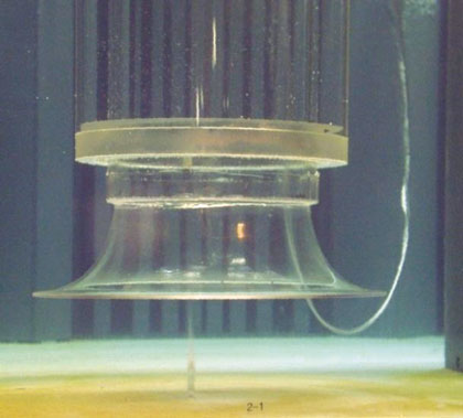
Figure 2: Air Drawing Surface Vortex
PUMP BAY DESIGN
The pump intake should follow the Hydraulic Institute Standards (HIS) for pump bay dimensions, minimum submergence requirements and maximum approach velocity requirements to prevent unacceptable free-surface and subsurface vortices. Figure 1 shows an unacceptable subsurface vortex emanating from the pump bay back wall, while figure 2 shows an air-drawing free surface vortex with an air-core. Both free-surface and subsurface vortices could induce unacceptable pre-swirl at the impeller entrance and vortices with air-cores could induce air entrainment degrading the pump performance and vibrations resulting in maintenance problems. The bay dimensions and minimum submergences recommended by HIS, are sometimes difficult to meet in the intake structure for a cooling tower because of space and the fore-bay design limitations. The strong flow patterns that may set up in the fore-bay can be corrected by a variety of flow correcting devices and may be needed to provide uniform approach flow to the pumps. A quiescent flow pattern upstream of the pumps will be the least detrimental to the pumps.
Often, pump intakes are designed prior to the selection of the pumps that will be used. This can cause some issues with the pump bay designs. The Hydraulic Institute Standards (HIS) recommend pump bay dimensions based on the entrance diameter of the pump bell, as indicated in figure 3. The submergence is specified as a function of Froude number of the flow (defined with the flow velocity at the bell entrance and bell diameter at the entrance). Consideration should be given at the initial design phase to accommodate a change in the pump used. Some common remedial designs that can be used to correct this problem if a redesign is not possible would be to add benching to the sides of the pump bay, or the addition of fillets and splitters to direct the flow more uniformly into the pump bell as shown in figure 3. It is recommended that the bay width fall within the HIS guidelines, and to only use these structures if detrimental flow patterns are found with a model study.
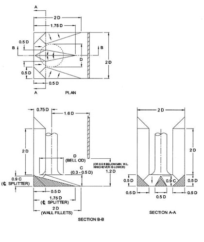
Figure 3: Common Fillet and Splitter Remedies (Note: D is the Pump Bell Entrance Diameter)
Due to limited space availability for the fore-bay cooling tower pump intakes, the approach flow to the pump bays may be skewed, especially if all pumps are not operational. Flow distributors and/or curtain walls are often needed at the pump bay entrances (within the bays) to help improve the flow patterns approaching the pumps, or to limit the debris that may enter the pumps. A curtain wall spanning the entire pump bay is shown in figure 3. Flow distributors may include a series of cylindrical or rectangular columns spanning the fore-bay before the pump bays. Both of these types of devices create a restriction in the flow and create a head loss (water level drop) in the system. These devices are intended to improve the approach flow conditions, but there remains the chance that the increase in head loss may not be acceptable in terms of minimum submergence to pumps.
When a trash rack or traveling screen is utilized in the pump bays consideration should be given to the area that is being used to screen debris in a manner to allow the majority of the flow to use the entire area of the screen. The use of the maximum area of the screen will minimize head loss due to blockage of these debris interceptors. An approach flow velocity to screens less than 1.5 feet per second is desired.
A LOOK AHEAD
In this series’ conclusion, we will examine another real-world example of interest illustrating the problem conveying flow from cooling tower to intake structure as well as the issues with poor approach flow patterns to the pump bays. Additionally, we will break down the problem with starving pumps of flow and look closer at the issues with poor approach flow patterns in the pump bays.
For More Information
Founded in 1894, Alden is the oldest continuously operating hydraulic laboratory in the United States and one of the oldest in the world. Alden has been a recognized leader in the field of fluid dynamics research and development with a focus on the energy and environmental industries. For more information, visit www.aldenlab.com.
____________________________________________
MODERN PUMPING TODAY, February 2017
Did you enjoy this article?
Subscribe to the FREE Digital Edition of Modern Pumping Today Magazine!