Ahydraulic model study of a recently designed intake structure showed that the conveyance of flow from the cooling tower basin to the intake structure fore-bay had a detrimental impact on the flow patterns to the pump bays.
PROBLEM CONVEYING FLOW FROM COOLING TOWER BASIN TO INTAKE STRUCTURE
The gate structure that was used was selected by the designer of the cooling tower basin, and sufficient thought was not given to the design of the gates. The gates were narrow and the flow exiting the gates entered the fore-bay as strong jets close to the water surface, creating supercritical flow regions within the fore-bay. The result was a turbulent water surface and a series of hydraulic jumps resulting in unstable flow to the pumps. The water surface profile in the fore-bay did not allow enough depth within the pump bays, the pumps were starved of water, and the system would not function properly. The turbulence also entrained air bubbles that reached the pumps. The solution to this problem was a redesign of the fore-bay geometry. Figure 4a shows the original design and 4b the modified design. The fore-bay was lengthened and the floor elevation change was made in steps because of the issue, and the flow became much more quiescent. The impact of the jetting from the gate geometry was greatly reduced and the problem was solved without changing the gate design. Had the intake structure designer selected the gates this issue may have been avoided. The use of the hydraulic model study to evaluate this problem saved the designer from constructing a prototype design that wouldn’t provide the flow to the pumps, and allowed them to evaluate and modify the design for a relatively small cost.
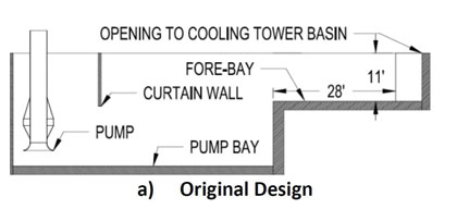
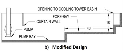
Figure 4: Modified Design with Expanded Forebay
ISSUES WITH POOR APPROACH FLOW PATTERNS TO THE PUMP BAYS
In another cooling tower intake structure the fore-bay design had problems in effectively moving the flow to the pumps. The pump bays were drawing flow from a forebay geometry that was much larger than the total width of the pump bays combined. This design created a strong flow separation, eddies, and pre-swirl conditions within the pump bays as shown in figure 5a. The addition of guide walls to direct the flow into the pump, as shown in figure 5b, made the flow much more uniform. The column type flow distributor was found to be detrimental due to high losses lowering the submergence at pumps, as discussed in the next section and was removed. Instead, a curtain wall was added within the pump bays (see figure 5b) to correct the surface vortex activity that was observed.
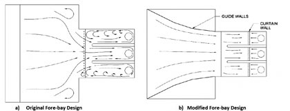
Figure 5: Modifications Involving Flow Guidance within Forebay (Note: Fillets and Splitters Removed for Clarity)
PROBLEM WITH STARVING PUMPS OF FLOW
The cooling tower intake structure shown in figure 5 also encountered problems with water levels that are too low, starving the pumps of water. Using a physical hydraulic model, a series of columns were placed at the entrance to the pump bays. The designer also wished to utilize a rather low water surface elevation in the intake structure. The combination of these two factors led to insufficient water levels due to flow distributor losses, and starving of the pumps. Column flow distributors generally require a low percent open area to be effective in redistributing flow and making it more uniform; but the losses induced by them may be too much as indicated in this case. The solution that was implemented in this case was the removal of the columns at the pump bay entrance, and to increase the minimum operating water surface elevation. However, with the cylindrical columns removed the flow was less uniform approaching the pumps and resulted in a large pre-swirl angle, as well as strong surface and sub-surface vortices. To correct for these problems a curtain wall was added to calm the water surface by generating an under flow and reducing surface velocities. The calmer water surface reduced the surface vortex activity, and the increased velocity near the floor weakened the subsurface vortices. Since the subsurface vortices were still objectionable based on the HI guidelines fillets and splitters were added to the pump bays to resolve the issue.
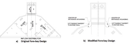
Figure 6: Modifications to Remedy Flow Separations in the Forebay
ISSUES WITH POOR APPROACH FLOW PATTERNS IN THE PUMP BAYS
One of the cooling tower intake structures that was investigated had issues with poor flow patterns in the pump bays that was created by the fore-bay geometry. In this design, shown in figure 6a, a rather abrupt contraction with sharp corners was used to guide the flow to the pump bays. This design led to a large flow separation and eddy (recirculation) forming just upstream of the pump bay entrances, near the walls that were designed to guide the flow. The result was that this eddy caused poor approach flow patterns in the pump bays. To correct for this problem a half cylindrical structure, as shown in figure 6b, was placed in the area of flow separation to help guide the flow into the pump bays more uniformly.
This device helped to improve the flow patterns but was not sufficient in itself to fully correct the flow patterns. A flow distributor was added that reduced the open area in the bay by 47 percent. This device redistributed the flow and made it much more uniform. As discussed earlier, the flow distributor should be used with caution, ensuring that the pumps are not starved by the increase in head loss.
CONCLUSIONS
In designing cooling tower pump intakes, the designer should be aware of a number of problems that can affect the hydraulic performance of the pump intake. The problems that are encountered may not initially be obvious, but can have some serious ramifications on the performance of the intake structure.
In general, the designer should make every effort to avoid large floor drops from basin to intake fore-bay floor that may result in free over falls and/or supercritical flow, gates at the basin outlet that are too small and result in high velocity jets and sudden area contractions at the fore-bay to pump bay junction. Also, steep floor slopes greater than 10 degrees should be avoided. Sufficient submergence at the pumps (HIS criteria can be used) should be available to reduce detrimental vortex severities and pre-swirl. The implementation of common remedies should also be considered when designing the intake. The use of curtain walls, fillets and splitters, as well as flow redistributors will help to improve approach flow patterns. Rounding of corners and providing guide walls will have an enormous benefit in reducing flow separations and eddies.
The best way to ensure that adverse hydraulic problems will not be encountered at the facility is to use a hydraulic model study to evaluate flow patterns, vortex severities, and pre-swirl. The use of a hydraulic model study to evaluate these problems and derive remedial modifications will help in the long run to reduce cost and maintenance of the facility. Potential major problems can be rectified at a much lower cost before construction rather than modifying a prototype design already constructed. The physical hydraulic model will also be useful in optimizing the location and size of flow correction devices that may be required in the prototype.
For More Information
Founded in 1894, Alden is the oldest continuously operating hydraulic laboratory in the United States and one of the oldest in the world. Alden has been a recognized leader in the field of fluid dynamics research and development with a focus on the energy and environmental industries. For more information, visit www.aldenlab.com.
____________________________________________
MODERN PUMPING TODAY, March 2017
Did you enjoy this article?
Subscribe to the FREE Digital Edition of Modern Pumping Today Magazine!