In the first part of this series, we illustrated how fluid pressure head is a function of pressure and density and how for every unnecessary foot of head the pump is adding more energy than the system needs, which results in the additional flow or throttling to dissipate the energy that occurs at a control valve. This higher energy naturally results in higher cost, added wear on the control valve, an increased risk of cavitation, and potentially more downtime for maintenance and equipment replacement.
GAUGE OR ABSOLUTE
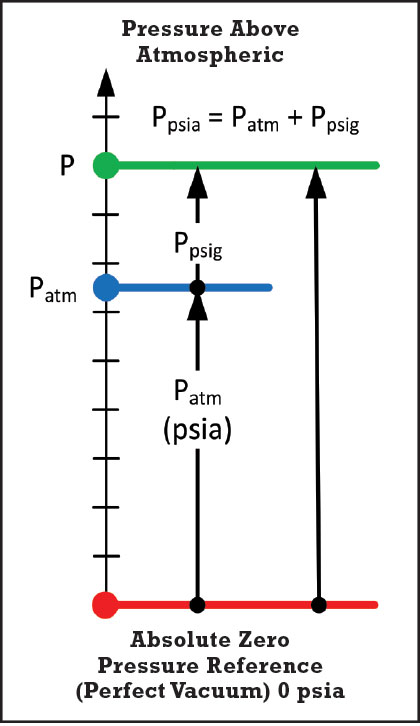
An important qualifier for fluid pressure is the distinction between absolute and gauge pressure. This distinction establishes the zero reference for values of pressure.

Absolute pressure (in units of psia, kPa a, bar a) uses the pressure that would exist when all atoms and molecules are removed from a given volume (absolute zero pressure) as the reference point. This condition is physically impossible to attain on Earth, but makes a good reference value for pressure. Pressure below absolute zero cannot be achieved. For example, many fluid properties, like vapor pressure and critical pressure, are tabulated using absolute pressure in units.
Gauge pressure (in units of psig, kPa g, bar g) uses the local atmospheric pressure as the zero reference. The most common type of pressure instrument compares the fluid pressure to the atmospheric pressure. Pressure below atmospheric (but above absolute zero) is referred to as a vacuum. A vacuum can be quantified as a negative value of gauge pressure but is typically expressed in units of inches of water column for slight vacuum, and inches of mercury for strong vacuum.

Figure 3: Gauge and Absolute Pressure
More often than not, when plant personnel are discussing pressure, “the pump discharge pressure is 125 psi,” the distinction between absolute and gauge is not made, but instead is assumed to mean gauge pressure because that’s where the pressure value is read from. Often, an abbreviated form of the pressure unit is used: “the pump discharge pressure is 125 pounds.” As long as everyone is on the same page, this lack of concise use of units won’t be a problem.
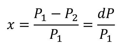
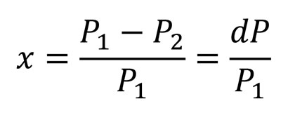
However, there are engineering calculations where the distinction between absolute and gauge pressure must be made. For example, when sizing and selecting control valves for compressible gas applications, the Pressure Drop Ratio (x) must be calculated from the inlet pressure (P1) and outlet pressure (P2) in absolute pressure units. The ISA 75.01 standard for sizing control valves defines the Pressure Drop Ratio as:

The use of gauge pressure in the equation will result in the wrong value for the Pressure Drop Ratio. For example: Patm = 14.7 psia, P1 = 50 psig or 64.7 psia, P2 = 25 psig or 39.7 psia.
Correctly using absolute pressure:

Incorrectly using gauge pressure:

An incorrect calculation for the Pressure Drop Ratio may make the difference between selecting the right control valve for the application or one that might result in choked flow at the valve.
DIFFERENTIAL PROPERTY OR PROPERTY AT A GIVEN LOCATION
Understanding the distinction between units that refer to a fluid property at a given location in the piping system and the differential between two locations is also important to the concise communication and proper use of values and units. Often in engineering it’s not the value of a fluid property at a given location that’s important, but instead the difference between two points.
For example, when designing and analyzing a piping system, one of the first things that must be established is the zero reference datum from which all vertical elevation measurements are made. This reference plane may be at sea level, the grade of the facility, the keel of a ship, the bottom of a tank, the centerline of the pump impeller, or any random elevation of your choosing. To properly apply the Bernoulli Equation, Head Loss can be determined from the difference in the fluid’s total hydraulic energy between two points in the system.

The total hydraulic energy includes the fluid’s Elevation Head (Z), Pressure Head, and Velocity Head. The individual value of the Elevation Head at both points is not important as long as both elevations are measured from the same reference plane.
KNOW YOUR ZERO
Piping systems are designed, built, and operated to transport fluids through various process equipment to change their properties in order to make a product or perform work. The energy content of the fluid must be elevated to move the fluid through the system.
In the design and operation of a piping system, costly mistakes that result in lost production, off-quality product, excessive downtime, environmental excursions, and costly re-work can be prevented by solid engineering understanding and concise communication and use of units, equations, and concepts.
Don’t let your piping system burn up in the atmosphere of Mars! Know your zero!
ABOUT THE AUTHOR
Jeff Sines is product engineer at Engineered Software, Inc., the leading software developer for piping systems worldwide. With over thirty years of experience in the software development industry, ESI’s portfolio includes award-winning PIPE-FLO®, PUMP-FLO™, and ESI Learning product lines. For more information, visit www.eng-software.com.
____________________________________________
MODERN PUMPING TODAY, July 2015
Did you enjoy this article?
Subscribe to the FREE Digital Edition of Modern Pumping Today Magazine!


