In all aspects of life, numbers are used to describe the amount of something, whether it’s the cost of a product, the distance between two cities, how fast you are driving, or how old your children are. But a number is meaningless unless it has two things: a unit and a zero reference datum. In science and engineering, miscommunication, confusion, and costly mistakes can occur when numbers are used without proper attention to units or their relationship to a reference point.
In September 1999, the $325 million NASA Mars Climate Orbiter disintegrated in the upper atmosphere of Mars because the navigation software produced output in Imperial units of pound-seconds (lbf·s) instead of SI units of newton-seconds (N·s). This error caused Trajectory Correction Maneuvers to place the orbiter on a path to enter the Mars atmosphere at an altitude of 37 miles (60 kilometers) instead of the intended altitude of 140 miles (225 kilometers). A minimum altitude of 50 miles (80 kilometers) was required for safe orbit around Mars.
Not all miscommunication is as costly as the Mars Climate Orbiter. However, expensive mistakes are commonly made here on Earth. When designing, installing, operating, and maintaining piping systems these mistakes often result in lost production, off-quality product, excessive downtime, environmental excursions, and re-work. It is crucial that communications be as concise as possible for all who are involved in any aspect of operating a process system, particularly those involved in extremely hazardous fluids and energy levels.
FLUID PROPERTY UNITS
There are numerous fluid properties that are used in the design and analysis of piping systems: pressure, temperature, density, viscosity, and specific heat capacity to name a few. Each property has a numerical value and unit that gives meaning to that property and allows it to be used to determine the operating conditions for the system. Understanding what the unit means, and when a unit conversion must be applied, is crucial to the appropriate use of the property.
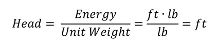
For example, when is a “foot” not a measure of distance? The pump industry characterizes the performance of a pump by how many feet of Total Head it produces. Head and feet in the study of fluid flow does not refer to distance or parts of your body, but instead is used to quantify the specific energy, or energy content per unit weight (or mass), of the fluid.
But even the definition of head has some nuances that are not obviously apparent and must be taken into account in order to properly use the numerical values associated with it.
COMPARING VALUES OF HEAD
A key concept with head is that its numerical value is referenced to the density of the fluid under consideration. One foot of head of a given fluid is not the same energy content as one foot of head of a different fluid. Consider two site glasses containing two different fluids separated by a liquid/liquid interface at Points 1 and 2, as shown in figure 1. In order for the two fluids to be in equilibrium at the interface, the total fluid energy at Point 1 (H1 due to the height of the column and density of Fluid 1) must be equal to the total fluid energy at Point 2 (H2 due to the height of the column and density of Fluid 2).
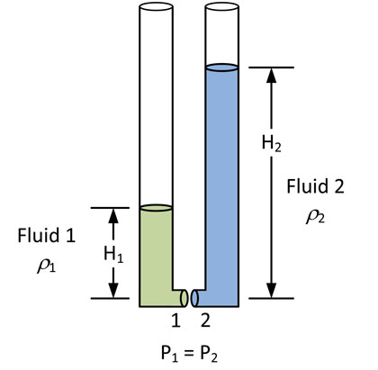
Figure 1: Fluid Pressure Head is a function of pressure and density.
But it’s obvious that H1 does not equal H2, so how can the two values represent the same amount of fluid energy? To reconcile this apparent discrepancy, it’s important to understand that H1 quantifies the amount of fluid energy at the interface in reference to the density of Fluid 1, while H2 quantifies the same amount of fluid energy but uses the density of Fluid 2 as the reference.
If the two fluids are in equilibrium with no flow, the static pressure at Point 1 must equal the static pressure at Point 2.
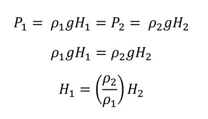
This density compensation adjusts one fluid’s numerical value of head so that it can be directly compared to another fluid’s head, in essence putting them on the same zero reference datum.
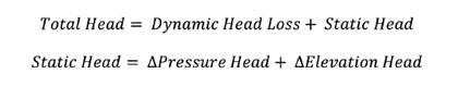
An example where this distinction may have an impact on the sizing and selection of a pump can be seen in figure 2. A pump must add sufficient energy to the fluid to overcome two aspects of fluid flow: energy lost due to friction (Dynamic Head Loss) and Static Head due to elevation and pressure differences between where the fluid is pumped to and where it is pumped from.
The pump itself does not know how much of its Total Head is used to overcome the Head Loss or how much goes to compensate for the Static Head. The pump “feels” a pressure at its inlet due to the configuration and Head Loss leading into its inlet as well as pressure at its discharge due to the configuration and Head Loss of the system at its outlet. In other words, the piping system tells the pump how much Total Head it must produce at a given flow rate.
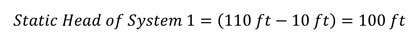
The static head that Pump 1 must overcome in System 1 can be calculated:
In System 2, a heat exchanger located at the 25 foot elevation heats up the water from 60 to 200 degrees Fahrenheit, resulting in a change in the density of the fluid from 62.38 to 60.14 pounds per cubic feet. Does Pump 2 feel the same amount of Static Head as Pump 1?
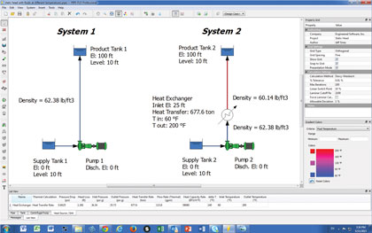
Figure 2: Systems with different values of Static Head modeled in PIPE-FLO® Professional.
Because the density of the fluid from the outlet of the heat exchanger to the liquid surface in the Product Tank in System 2 is less than System 1, the pressure felt at the 25 foot elevation due to this 85 foot column of water will be less than the pressure at the same location in System 1.
The Static Head felt by Pump 2 must include a portion of the system that is density compensated because the water flowing through the pump is at 60 degrees Fahrenheit:

This difference of 3 percent in Static Head between System 1 and System 2 may not be significant enough to result in over-sizing the pump in System 2, especially if a design margin of 15 to 25 percent is added prior to pump selection. But every unnecessary foot of head means that the pump is adding more energy than the system needs, which results in the additional flow or throttling to dissipate the energy that must occur at a control valve. That equates to higher energy cost, more wear and tear on the control valve, a greater susceptibility to cavitation and choked flow and potentially more downtime for maintenance and equipment replacement.
ABOUT THE AUTHOR
Jeff Sines is product engineer at Engineered Software, Inc., the leading software developer for piping systems worldwide. With over thirty years of experience in the software development industry, ESI’s portfolio includes award-winning PIPE-FLO®, PUMP-FLO™, and ESI Learning product lines. For more information, visit www.eng-software.com.
____________________________________________
MODERN PUMPING TODAY, June 2015
Did you enjoy this article?
Subscribe to the FREE Digital Edition of Modern Pumping Today Magazine!