


On March 11, 2014, in the LinkedIn blog “American Water Works Association,” Riley Vittitoe, the general manager for the water utility of Topeka, Kansas, posted a curious question: “When do most water main breaks occur?” One of the most interesting comments posted on the blog was that one respondent noticed that water main breaks in his system disappeared after he installed variable frequency drives on his system pumps. Although this answer was one item of many mentioned, it was interesting. Other causes listed in the blog indicated that improper bedding conditions, swelling or shrinking of the soils, and seasonal factors contributed to the frequency of breaks. Other commenters suggested that large changes in demand also contributed to the frequency of breaks.
Changes in demand, and the starting and stopping of system pumps, can create pressure waves in all types of pipes. This article will look at some of the effects of pressure waves and how they can damage a piping system.
THE BIRTH OF A PRESSURE WAVE
First, when we change the flow in a pipe, it creates a pressure wave in that pipe. Depending upon the diameter of the pipe, and the length of the pipeline, the pressure wave can, by itself, cause pipe ruptures, and can generate very large forces.
The basic equation of motion from Newton’s First Law reminds us that force is equal to mass times acceleration. Acceleration is the change in velocity, and the mass is the amount of liquid in the pipe. For long pipes, this can be a very great force because of the length of the pipe. A quick example follows:
Given a cast iron transmission main 12,000 feet (3650 meters) long 16-inch (406.4 millimeter) nominal Schedule 150 pipe (actual dimensions from the Mueller catalog are diameter of 16.32 inches [414.528 millimeters] and wall thickness is 0.54 inches [13.716 millimeters]) diameter pipeline full of water, carrying 6500 gallons (24 cubic meters) per minute moving at 10.4 feet (3.171 meters) per second.Compute the pressure rise from valve closure or pump failure.
The force exerted is the sum of the density times the quantity times the change in velocity. Note that this is simply the weight of the liquid in the section divided by the force of gravity. Written as an equation:
![]()
Where F is the force, and ρ is the density of the liquid, Q is the quantity, and ΔV is the change in velocity. Looking at some terms are re-arranging and making some substitutions, we get:
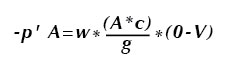
Where –p’ is the pressure force, w is the weight of the fluid, A is the area of the pipe, and c is the velocity (celerity) of the pressure wave. The pressure wave reduces the velocity in the pipe to zero as it passes each section. This is much in the same way as a freight train slows down: The engine leads, and as it slows the resistance force is transmitted through each coupling until the entire train is slowed.
If the pipe is rigid, the velocity or celerity of the pressure wave can be calculated by some additional manipulation (not shown) to be
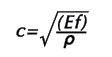
Where Ef is the bulk modulus of elasticity of the liquid (compressibility of the liquid), and ρ is the density. For water, the bulk modulus of elasticity is approximately 313,000 psf, and the calculation, which assumes a totally rigid pipe wall is c=√(313000*144/1.94) = 4820 feet (1469.5 meters) per second at 60 degrees Fahrenheit (15.56 degrees Celsius).
MATERIAL CONSIDERATIONS
But if the pipe is non-rigid, cast iron, steel, or plastic, some of the energy is dissipated by pushing on the walls of the pipe and stretching it a bit. In steel and cast iron materials, this is small to negligible, but in PVC it can be significant. This stretching action also slows down the pressure wave.
The accurate formula for the velocity of a pressure wave in a non-rigid pipe including steel, cast iron, and plastic is shown below.
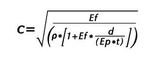
Where Ef is the bulk modulus of the liquid, Ep is the bulk modulus of the pipe, d is the diameter and t is the thickness. The density of the fluid is ρ. If we apply the actual values to our example above, the speed of the pressure wave becomes: 3342 feet (1019 meters) per second. The pressure wave will travel the length of our 12,000 feet (3657.6 meters) of pipe in 3.59 seconds. Any valve closure or pump failure which has a time less than 3.59 seconds will generate a pressure wave or water hammer in the pipe.
If a pipe has a length of L , the water hammer will reflect off of a reservoir or another closed valve, and the travel time for the return wave will be twice the length of the pipeline divided by the speed of the wave, or in this case 6.34 seconds. It is important to note that the return wave will be negative, and it will be reflected from the closed valve as a positive wave of slightly lesser magnitude, and travel back and forth as a positive and negative waveform until it finally dissipates.
For our pipeline example from above the increase in pressure will be given by
![]()
and the resulting numbers are h=3342*10.4/32.18=1080 feet of head or (449.6 PSI or 3100 kpa).
If we calculate the stress on the piping using the accepted hoop stress formula, the 469 psi increase will generate a stress (over and above the stress due to the existing pressure) in the pipe wall, of
![]()
The additional stress is equal to 469.6*8.18/0.54 = 9655 psi increase in tension on the pipe wall. The yield strength of cast iron, depending upon the type is between 25,000 psi and 50,000 psi. If the wall has been corroded and is thinner, the pressure at that point could exceed the tensile strength of the cast iron, resulting in a dramatic release.
BULK MODULUS OF LIQUIDS AND SOLIDS
Below are some values for the bulk modulus of liquids and solids used in piping systems.
[row]
[col width=”six”] 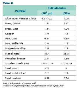 [/col]
[col width=”six”] 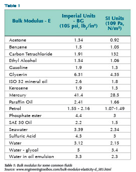 [/col]
[/row]
A Question and Some Answers
The sudden stopping of a fluid in a pipeline can cause high pressure waves. OK, so how do we prevent water hammer?
Increase the valve closing times will help. An initial calculation suggested above where the valve closing time is greater than twice the length of the pipe divided by the celerity of the wave will greatly reduce the incidence of water hammer. Similarly, providing pumping stations with variable speed drives and standby generators to reduce sudden starts and stops of the fluid will also help prevent water hammer.
For long pipelines, a surge tank is recommended to help reduce water hammer. Even in some houses, this can be as simple as a tee and a pipe stub filled with air near the faucet or valve subject to sudden closure. The stub should be vertical, and may or may not contain an air valve to allow it to be filled with air from an external pressure tank. Similarly, a pressure tank which is filled with air in small water systems located immediately following a pump can easily reduce water hammer from the starting and stopping of the pump while it maintains overall system pressure. But it won’t reduce water hammer occurring on the system pipes leading from the tank to distribution points.
ANALYTICAL SOLUTIONS ABOUND
There are a number of computer programs which model piping systems and can model water hammer and help one to figure out how to reduce it. Some of these programs will work together, others are commercially available, and some are freeware.
[row]
[col width=”six”]
[/col]
[col width=”six”]
[/col]
[/row]
■ ■ ■
[divider]
ABOUT THE AUTHOR
David L. Russell, PE, is a chemical and environmental engineer and the founder of Global Environmental Operations, Inc., a specialty environmental consulting firm serving clients all over the world. Mr. Russell is an in-demand consultant for projects ranging from environmental process designs and hazardous wastes to water systems and wastewater treatment. He can be reached at 770.923.4408 or by visiting www.globalenvironmental.biz.
MODERN PUMPING TODAY, March 2014
Did you enjoy this article?
Subscribe to the FREE Digital Edition of Modern Pumping Today Magazine!