By Indira Rajagopal, Metrix
A centrifugal air compressor is a rotating machine that uses centrifugal force to develop pressure for different applications. It accelerates air from the center of the impeller and then slows it down in a diffuser. During the air expansion process, the velocity energy is converted into potential energy and consequently the air is pressurized.
Multiple stage, particularly three‐stage, centrifugal air compressors are very common in a plant. Each single stage can render pressure increases of 2:1 to 3:1, and a sequential third stage will end up with about an 8:1 pressure increase. Other advantages of three‐stage compressors include the convenient control of temperature and moisture after each stage of compression. A centrifugal air compressor is a complex rotating machine made of many different components. Figure 1 illustrates some of them:
- Motor
- Bull gear with pinion gears to drive air compression stages.
- Inlet throttling valve or inlet guide vanes (IGVs)
- First air compression stage
- Intercooler 1
- Second air compression stage
- Intercooler 2
- Third air compression stage
- Aftercooler
- Blow‐off valve
- Check valve
- Control panel
APPLICATION
Modern centrifugal air compressors are compact, efficient, and reliable. Typically, they are mounted on a common base with motor, gears, coolers, piping and controls all integrated. A compressor controller is used to manage the air compressor capacity and reliability at a relatively constant outlet pressure. Recent advanced technology of centrifugal air compressor has brought tremendous benefits to users, such as oil‐free air delivery, simple installation, low‐cost operation, and easy maintenance. As a result, a centrifugal air compressor is extensively used in various industrious and commercial applications including the following:
- Air separation
- Oil refining
- Power generation
- Chemical processing
- Food and beverage
- Petrochemical
- Plastics
- Electronics
- Pulp and paper plant
- Textiles
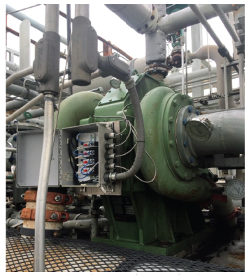
One example of applications in a chemical processing plant is shown in figure 2.
FAILURES AND CAUSES
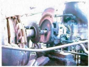
Catastrophic failure of the compressor can bring serious consequences to plant operations, such as failure of other equipment, safety hazards, downtime, lost production revenue, expensive repairs, and health issues. Compressor failures can be from different reasons, but the most common one is the mechanical component failure linked to unbalance, misalignment, fatigue or off‐design, insufficient or improper lubrication, seal failures, and the build‐up of foreign materials. Figure 3 shows a catastrophic compressor failure at a refining facility, which caused significant downtime and production losses.
The shaft is the critical rotating part to transmit motion and carry forces within the compressor mechanism. The bearings are attached to the housing to provide both radial and axial support to the shaft. Therefore, vibration in the shaft or bearing housing will be the first symptom and genuine indicator of many problems of the centrifugal air compressor system.
ASSET PROTECTION
Centrifugal compressors are vital assets to many production facilities and plants are relying on them for operation. It is important to have certain machine protection mechanisms to provide healthy status of the compressor and prevent catastrophic failure. Vibration monitoring is one of the most common methods that can detect many faults before they escalate into serious problems. The implementation of vibration monitoring can lead to many other benefits, such as:
- Increase uptime and production output
- Eliminate unexpected repair and unscheduled downtime
- Optimize maintain scheduling and machine performance
- Improve financial performance
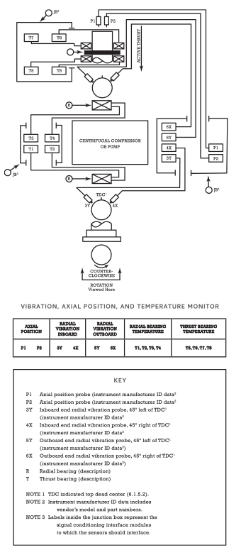
The American Petroleum Institute (API) is a big advocate in developing equipment monitoring standards, and the API standards have been widely accepted by many rotary machine users. In 1970, API accepted proximity probes as measurement devices for determining the acceptable shaft vibration during factory acceptance testing. Known as the API 670 standard, it was revised later to add content concerning temperature and material for casing vibration measurements on gearboxes. In 2001, the API 670 standard was revised again and titled Machinery Protection Standard. API 670 has become the most widely applied standard for vibration monitoring in the world as it generally reflects recognized “good engineering practices” for vibration monitoring systems. In figure 4, API suggests that a minimum of two axial position and two pairs of radial vibration probes (X and Y) shall be installed for a centrifugal compressor with fluid film bearings for shaft vibration monitoring. Experience also recommends a minimum of one set of seismic vibration sensors to be mounted on the bearing case to monitor the overall housing vibration.
PROTECTING COMPRESSORS AS THEY WORK
Metrix pioneered the concept of technology innovation and affordable machinery protection to its customers. Metrix supplies a complete vibration solution with both proximity and seismic product lines to meet different requirements from a variety of applications. The combination of the digital proximity system products MX2033 driver and MX2034 transmitter, as well as the SA6200A Accelerometer or seismic transmitter ST5484E can protect your compressor and provide many benefits to your business.
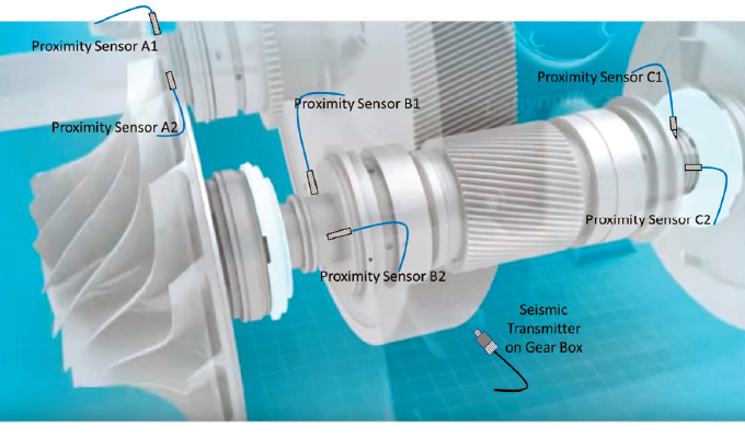
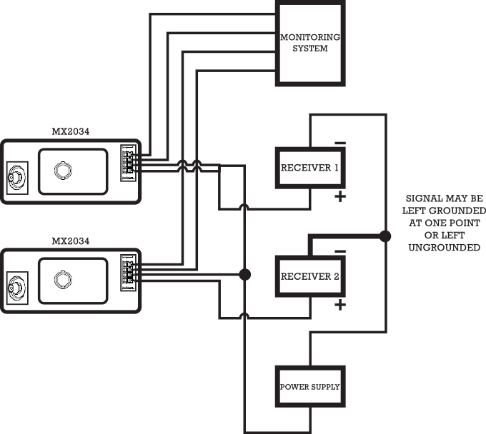
To protect a three‐stage centrifugal air compressor, it is recommended to install at least one MX2034 probe system per impeller to measure radial vibration and at least one seismic transmitter ST5484E for gear box vibration. The 4‐20mA signal can be routed to a PLC/DCS Control System and the buffered raw signal can be available for diagnostic analysis. An improved system would use a pair of XY transducers at each bearing/seal. The typical installation and wiring are shown in figures 5 and 6.
EASY ADAPTABILITY AND USE
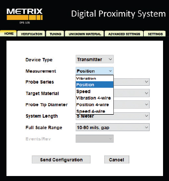
To protect the centrifugal air compressor in a greater degree, it is recommended to monitor the axial position and the speed of motor/impeller shaft as well. This can be achieved through configuration and utility software, such as the Metrix DPS system shown in figure 7.
Metrix MX2034 proximity transmitters have the capability to measure these parameters. The digital configurability of the MX2034 makes it easier for users to use any mode in the field to meet different requirements in your machine protection system.
FOR MORE INFORMATION
Metrix pioneered the concept of simple, affordable machinery protection with its mechanical vibration switch offerings, revolutionary 4-20mA vibration transmitters, robust high-temperature velocity sensors, and innovative impact transmitter technology for reciprocating machinery. Metrix has been ISO-9001 certified for more than twenty years, which ensures that it never loses sight of quality and continuous improvement of its manufacturing processes. For more information, visit www.metrixvibration.com.
MODERN PUMPING TODAY, August 2021
Did you enjoy this article?
Subscribe to the FREE Digital Edition of Modern Pumping Today Magazine!