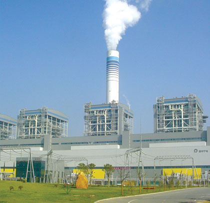
To meet China’s growing need for electric power generation, the Guohua Ninghai Power Plant has a total planned operating capacity of 4 x 600 MW (Phase 1) (see figure 1). The plant is located south of Shanghai in Ninghai township, Ningbo city, Zhejiang province and serves the electric power needs in the region.
The Ninghai plant relies on coal-fired steam driven turbines to generate electricity with six sets of HP-983 medium speed coal mills supporting a tangentially corner-fired boiler. The plant’s large production operations are complex.
Coal is first fed from silos at the plant to coal mill pulverizers, which grind the coal into a fine powder. A fan blends and forces a primary flow of mixed ambient “cold” air and pre-heated “hot” air into the coal mill. This air is mixed with the coal powder creating a combustion air supply for a furnace heating water in a boiler. The boiler produces steam to drive power-generating turbines. The plant’s sophisticated, energy efficient boiler requires accurate and responsive air flow measurement for its control system.
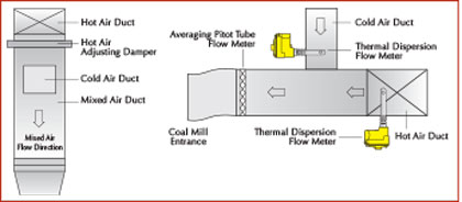
Figure 2: Primary air duct at coal mill entrance
THE PROBLEM
The boiler’s steam production efficiency is controlled by adjusting a precise flow of blended primary ambient air and pre-heated air which flow from separate ducts. Each of the duct air flows is controlled by louvered dampers located inside the ducts. The primary air, which is a precise blend of cold and hot air, flows into the coal mills and afterwards the boiler. Accurate, responsive and reliable air flow measurement is critical to the automated control of the dampers and the efficiency of the boiler, which also ensures safe operation of the boiler and reduces plant operation energy costs.
The temperature of the pre-heated air fed to the boiler is 518 degrees Fahrenheit (270 degrees Celsius) and the primary ambient air temperature is 86 degrees Fahrenheit (30 degrees Celsius). The size of the primary air duct is 47 by 47 inches (1200 by 1200 millimeters), the pre-heated air duct is also 47 by 47 inches (1200 by 1200 millimeters), and the ambient forced draft air duct is 20 by 31inches (500 by 800 millimeters).
The air flow to the coal mills and into the boiler is controlled by the plant’s distributed control system (DCS), which requires accurate and responsive air flow measurement data to control the dampers and keep the primary air flow to the coal mill entrance at precise and efficient levels. Figure 2 shows the primary air duct at the coal mill entrance.
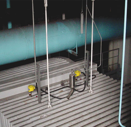
Figure 3: Thermal mass flow meter in cold air duct
EVALUATING POTENTIAL SOLUTIONS
Engineers from the China Electric Power Research Institute (CEPRI) and the Guohua Ninghai Power Plant researched several flow meter technologies for accuracy and responsive performance and the overall suitability for the unique application conditions in their air feed lines. Then they further considered existing installations and reference applications at other power plants in China. From this criteria, they narrowed their choices to two technologies for further evaluation, thermal mass flow meters (a.k.a thermal dispersion) and averaging pitot tube flow meter (a.k.a. differential pressure, dP).
Both of these technologies would be further evaluated and compared with actual on-site installed performance testing. With the large duct sizes involved, both of these technologies were deployed in a multi-point design. The engineers determined that the key criteria for the flow meter technology ultimately selected would be the one that was most accurate, responsive, and impervious to large temperature fluctuations that allowed them to best control the air flow automatically via the dampers in the ducts using the plant’s DCS. These application criteria can be difficult to achieve because of the large cross sectional area of the air ducts and the temperature stratification in the primary air duct caused by the mixing of the pre-heated and ambient air.
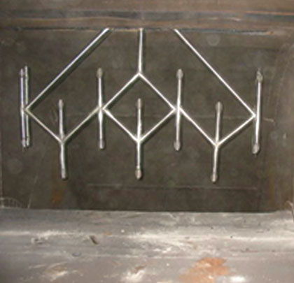
Figure 4: Averaging pitot tube flow meter in primary air duct
INITIATING FLOW MEASUREMENT TESTS
For the flow measurement test program, the two different types of flow meters were installed on Coal Mills C and D that feed Boiler 3. Thermal mass flow meters with multiple sensing points were installed in each of the pre-heated and ambient air ducts. This installation eliminates the large temperature fluctuations that are present in the main primary air duct due to the mixing of the pre-heated and ambient air. It also provides a more precise and responsive damper control within the air ducts. Figure 3 shows the thermal flow meter that was placed in the preheated air duct. The averaging pitot tube flow meter was installed in the main primary air duct downstream from the preheated and ambient air ducts. Figure 4 shows the averaging pitot tube flow meter in the primary air duct.
The output readings from the two thermal mass flow meters were compared to the averaging pitot tube flow meter and to the changes in the dampers. Based on the result of the test program, the thermal mass flow meters provided the best system control. The thermal mass flow meters on the duct for Boiler 3 provided an accurate and responsive output of the air flow rate, which was consistent with the damper positioning. See figure 5 for the Mill D recorded air flow measurements.
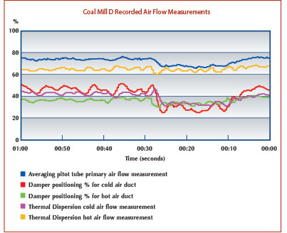
Figure 5: Test data for thermal mass flow meter
COMPARING THE RESULTS
Both the averaging pitot tube flow meter and the thermal mass flow meter tracked the damper positioning changes in this test and their air flow readings were within 1 percent accuracy of each other. Although the averaging pitot tube flow meter provided a similar accuracy and was responsive, its accuracy was adversely affected when the air flow pressure dropped. See figure 6 for the Boiler 3 Mill C recorded air flow measurements at low pressures.
The tests showed the flow rate output of the thermal mass flow meter matched the set position of the cold and hot air dampers, and the thermal mass flow meter provided the response time required of the automatic control feedback loop within the DCS. The thermal mass flow meter’s responsiveness was enhanced by an anticipator algorithm programmed into the DCS. The DCS’ PID parameter proportion factor was adjusted from 0.3 to 0.4 and the integration factor was reduced from 300 to 150. The accuracy performance of the averaging pitot tube flow meter, however, was greatly degraded by low air pressure conditions and low air flows.
Due to the low pressure in test shown in figure 6—Mill C, the averaging pitot tube flow meter did not track well with the damper position changes. In addition, averaging pitot tube flow meters require significantly more maintenance because their sensor design includes small air inlets, which can clog in the fly ash laden air flow inside the ducts. A plus for the thermal mass flow meters is they do not have small air inlets nor any moving parts, so they impervious to the fly ash laden air flow conditions and do not require routine or preventative maintenance.
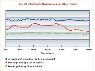
Figure 6: Test data for averaging pitot tube flow meter
THE SOLUTION
After completion of the test program, Fluid Components International’s (FCI) Model MT86 Series Multi-Point Thermal Mass Flow Meters (see figure 7) were selected for use at the Guohua Ninghai Power Plant. These precision air flow meters are installed and operating around the world in numerous electric power generation plants in similar applications because of their accurate, stable and reliable flow measurement over wide temperatures and variable pressures.
The FCI Model MT86 Series Multi-Point Thermal Mass Flow Meter can be supplied with up to eight discrete thermal mass flow sensors. These sensors can be installed along a single probe assembly or on multiple probes, whatever is optimal for the application and installation conditions. The MT Series is ideal for use in thermal and nuclear electric power generation and other heavy process or manufacturing industries with large diameter pipes or large duct applications It provides excellent air and gas flow measurement performance in applications such as these coal-fired combustion air systems as well as in HVAC systems, flues, and stacks.
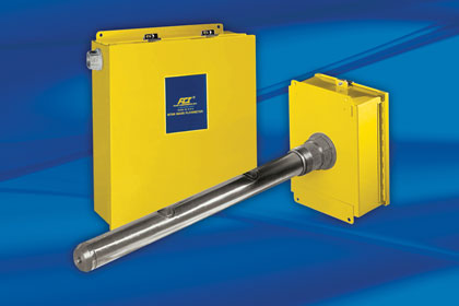
Figure 7: FCI MT86 Series Flow Meters
VERSATILE AND RELIABLE
MT Series Flow Meters are highly versatile, with a wide turndown range available from 5:1 to 1000:1 and flow sensitivity from 0.25 SFPS (0.08 NMPS) to 150 SFPS (45.7 NMPS). With its smart digital flow transmitter and advanced thermal dispersion flow sensing element(s), the MT86 Series, and its sister product MT91, meet a wide range of environmental monitoring requirements worldwide, including CEMS and QAL1.
They are a no-moving parts design with no orifices to plug or foul, FCI’s thermal mass flow sensing technology places two thermowell protected platinum RTD temperature sensors in the process stream. One RTD is heated while the other senses the actual process temperature. The temperature differential between these two sensors is measured and is directly proportional to the mass flow rate of the fluid (see figure 8). The sensor outputs are fully temperature compensated resulting in high accuracy and repeatability in changing media and ambient installation conditions. Outputs include multiple 4-20mA and relays and units can be powered by either AC mains (85-265 Vac) or 24Vdc.
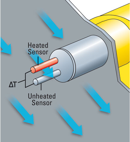
Figure 8: Thermal dispersion principle of operation
CONCLUSIONS
After testing and evaluating both flow meter technologies, the engineers from CEPRI and the Guohua Ninghai Power Plant solved the challenge of finding the most accurate air flow measurement technology which would be responsive enough for automatic damper control of the mix of preheated and ambient air flowing into the coal mills. The FCI thermal mass flow meters air flow accuracy and responsiveness provided the necessary flow data to automatically control the dampers and maximize the efficiency of Boiler 3. Their non-clogging sensors and rugged design ensured the lowest overall maintenance and longest service life. ■
_________________________________________________________________________
ABOUT THE AUTHORS
Hu Yaqi is an automation and process control engineer for Zhejiang Guohua Zheneng Power Generation Co., Ltd. and Steve Craig is a senior engineer at Fluid Components International LLC (FCI). For more information about the MT86 Series Flow Meter, visit www.fluidcomponents.com.
_________________________________________________________________________
MODERN PUMPING TODAY, October 2013
Did you enjoy this article?
Subscribe to the FREE Digital Edition of Modern Pumping Today Magazine!
![]()


