By Simon Seereiner, Weidmuller
Efforts to use Ethernet as a fieldbus alternative first immerged in the late 1990s. Seamless Ethernet networking from the control unit to the IT world offers huge advantages. For instance, the fill level of a tank can be reported directly to both the system control unit and to the purchasing department, without the need for gateways or a duplicate infrastructure for the control unit and IT. The introduction of the Industrial Ethernet and its defined response time conquered the IT standard as well as time-critical applications such as fast-running machines.
However, Ethernet remained a data highway that became increasingly faster and broader. For simple sensors, the technology is too costly and over dimensioned. The current RJ45 connectors and cables are not ideal for industrial use at field level for connecting the sensors. Complex encapsulation up to the sensor is too expensive and is often unfeasible due to lack of space. A further obstacle is the maximum cable length of over 325 feet, as well as the need for two-pair or four-pair cabling. This is insufficient for a widely-networked warehouse or for materials handling. Support comes in the form of an Ethernet standard that does not need to offer the high data transfer rates of the IT world, yet combines long cable lengths with a compact design as well as simple and robust cabling: Single Pair Ethernet, or SPE.
At first glance, it is a “downwards” extension of the existing Ethernet standards. With lower data transfer rates, it conflicts with the constant “faster and shorter” requirements in the IT world. However, many applications are not making full use of the capacities that are now available, in particular sensor technology. Sensors are currently connected via fieldbus gateways, and some are even connected over two levels to an additional sub-bus. In such cases, a continuous Ethernet connection delivers considerable technical and economic benefits. SPE also offers further advantages that are covered in the following sections.
MOTIVATION AND BENEFITS OF SPE TECHNOLOGY
Instead of two or four pairs of wires, SPE requires just one pair of wires. The impetus for this development came from wiring systems in the automotive industry, where cabling currently accounts for a great deal of the vehicle’s weight—and this trend is rising rapidly. This requires an infrastructure that can deliver high performance with as few cables as possible. There are similar expectations within industry as the number of intelligent end devices in the plant is increasing; however, the amount of available space is not—in fact, it is quite the opposite. As more and more sensors need to be integrated into machines and systems, the cabling must therefore be designed for industrial use, and be both compact and simple. Moreover, they are installed in extreme places such as robotic arms, where mechanical flexibility and weight play an important role—i.e., lightweight cables with a small outer diameter and low bending radii are essential. This kind of structure will also reduce the costs, as less material needs to be installed. It also makes it easier to extend an existing system than with eight-wire cables. With the thinner and lighter cables, more Ethernet channels can be housed than before in existing cable runs.
The physical properties and transfer rates are defined internationally by different standardization bodies. These new Ethernet versions are also being met with a great deal of interest in automation technology, as SPE meets the requirements for industrial communication in the digitalization era. The transfer rates of 10 megabits per second with a transfer length of 3,280 feet up to 1 gigabit per second with a transfer length of 131 to 328 feet are completely adequate, even for sophisticated sensors. Scanners and cameras for monitoring or for detecting a component’s type and location can also be continuously integrated into the network via Ethernet. The achievable response times even allow TSN (time-sensitive networking) applications. Another major advantage of SPE is the possibility of supplying power to the connected peripherals via PoDL (power over data line).
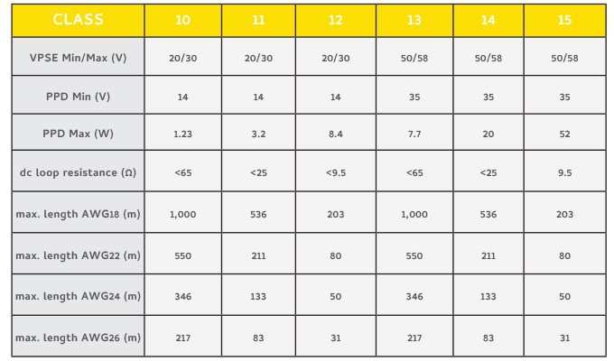
PoDL makes up to 60 Watts of power available to the PSE (power source equipment). This allows the sensors to be supplied both with energy and with a data interface, even under extremely cramped conditions. An additional, separate supply line is not required. The IEEE has defined a classification into different power classes for this purpose. Since classes 1–9 are already assigned to POE, the power classes for PoDL start at 10. Table 1 describes the resulting outputs for different supply voltages at the end device depending on the length and the cross-section of the cable line.
Additionally, PoDL opens up further applications for SPE. In addition to building infrastructure, this includes particularly demanding applications in potentially explosive environments. This means that SPE is also attractive for process technology. There are therefore virtually no applications for which this standard does not provide new impetus: whether in IT, production or under extreme conditions, the infrastructure is easy to install thanks to the miniaturized connectors and the single pair cables.
SPE thus meets the fundamental requirements of IoT and Industry 4.0 applications—continuous, intelligent networking of an application across all levels, scalable, deterministic, and fully compatible. In a nutshell, each one can communicate with each other.
STANDARDIZATION: THE KEY TO SUCCESS
On the basis of these benefits, renowned experts from the connector industry, automation technology, and the cable industry and have joined forces to develop international standards for this technology. This clearly demonstrates the importance of standardization, as interoperability, and thus the long-term success of SPE, can only be ensured through international standards.
It goes without saying that many bodies are involved in the international standardization of such an important technology. At this point, only the key bodies involved are mentioned: The application and the definition of the transfer channel is being processed by the IEEE 802.3 (Institute of Electrical and Electronics Engineers; Ethernet Working Group). ISO/IEC JTC 1 SC25 WG3 (International Electrotechnical Commission, Interconnection of Information Technology Equipment, Working Group 3: Customer Premises Cabling) describes the transfer requirement and its parameters for passive cabling structures in industry, in buildings, smart homes, and computing centers. The requirements of mechanical and electrical properties are ultimately defined by IEC SC 48B Electrical cap connectors and IEC SC 46C Wires and Symmetric Cables. There are fixed agreements between IEEE 802.3 and ISO/IEC that define the respective tasks.
For the IEEE 802.3cg (SPE 10 megabits per second) project, connectors and their electrical properties were defined for the first time in the IEEE environment. They are explained under the point on MDI (medium dependent interface). The MDI is the interface to the active components. The passive cabling structure is not described here. The technical properties that a connector or contact point must comply with for this application are described there. In a sub-item, the current version of the IEEE document describes possible connectors that can be, but do not have to be, used on the MDI. This is occasionally misrepresented in publications. Though it is crucial for the manufacturer and the user to recognize that this is an option (“may be used”) and not a regulation. Other connectors can also be used, if they meet the electrical properties of IEEE 802.3cg.
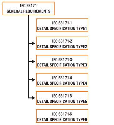
The connectors for Single Pair Ethernet are defined in the IEC 63171-X series of standards. The general electrical requirements of the interfaces can be found in the basic standard IEC 63171. The design of the mating faces and thus the mechanical requirements of the connectors are described in the subordinate series of standards. The basic standard could perhaps be likened to the engine and the standard series as the different car bodies.
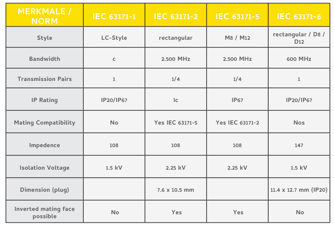
The connectors defined in the series of standards IEC 63171-1 to -6 have different mating faces, dimensions, and mechanical properties. Currently, neither IEC 63171-1 nor IEC 63171-6 refers to the basic standard of IEC 63171. As a result, there are different mechanical requirements and different electrical requirements. The key differences of the standardized connectors are listed in Table 2.
The connectors in accordance with IEC 63171-2 and IEC 63171-5 even observe stricter values. For example, they have a dielectric strength up to 2.25 kV DC. Finally, it should be mentioned that the use of connectors described as “may be used” in the IEEE 802.3 environment only relate to the 10 megabits per second application. Applications in the range 100 megabits per second, 1,000 megabits per second, and MultiGig are not affected by this. Therefore, the user is obliged to select the right connector for the application.
The ISO/IEC 11801-x series of standards describes the generic cabling structure for different environments. This is also being expanded due to the new SPE applications. It defines the same connectors as in IEEE 802.3cg. A “may be used” connector is defined in the ISO/IEC as a “shall be used” connector at the TO (telecommunication outlet). There is thus a fixed definition of the mating face for the TO.
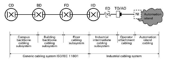
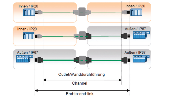
In figure 2, it is apparent that the TO represents the connection between automation and the factory hall. The specification for the mating face thus refers to applications outside of automation and, therefore, also to the connection of the automation island with generic cabling. The TO is, therefore, only described in the generic cabling in accordance with ISO/IEC 11801. Except for generic cabling, a TO is not used in PROFINET environments.
PROFINET and other industrial communication protocols define pure point-to-point cabling in their guidelines. Even the definition of the channel was not taken from generic cabling, instead a channel definition that has been adapted to the industrial environment was derived with the end-to-end link.
The normative process is currently underway but has not yet been completed. The claim that the market had already agreed upon a mating face, as was made by some manufacturers and is often mentioned in the trade press, is categorically incorrect. Important and powerful user organizations, such as PROFINET, are currently forming their own opinion and will deal with this subject area in the future.
A LOOK AHEAD
In next month’s conclusion to this article, we’ll examine SPE developments specifically introduced by Weidmüller. As you might expect, the connector is the first step. Plus, we’ll look at even greater flexibility with a four-chamber solution.
FOR MORE INFORMATION
Simon Seereiner is head of product management for sensor-actuator interface and industrial ethernet and cable harnessing. Since 2005, he is expanding the range of solutions for the passive, industrial networking of the Weidmüller Group. In addition, Seereiner works in various national and international committees for industrial networking. For more information, visit www.weidmueller.com.
MODERN PUMPING TODAY, December 2021
Did you enjoy this article?
Subscribe to the FREE Digital Edition of Modern Pumping Today Magazine!