By Walt Prentice, Applied Flow Technology
When you think of processing plants, you may think of oil, its derivatives, and other chemical products. After all, the end-product is what ultimately matters to consumers; it is what has monetary value. The goal is (and should be) that product. However, there are whole disciplines dedicated to the backend functionality that rarely get public attention: utilities and offsites. Without functioning utilities, the money-maker might as well remain undiscovered, raw materials.
A colleague who previously worked in a utilities division of oil and gas, opened my eyes more to the subject. These engineers hold an honorable position, bearing much of the responsibility without common recognition. Even more impressive is they are given much less insight into their systems than the process side. It is not uncommon for utilities to lack any controls, meters, or updated layouts. The systems are usually more than half a century old, which also reigns true for the main processes, but without the same insights available. Rather than constant flow metering, utility engineers get annual flow surveys. Once a year, they receive the great privilege to record a flow rate.
With the lack of basic information most of the time, how can they know what is going on, let alone plan for expansions and other changes?
The saving grace lies in computer modeling. Flow analysis software exists for nearly any system, from liquids to gases to two or three-phase, and from steady-state to transient. Let’s narrow our focus to a single steady-state utility, cooling water, and how modeling brings invaluable solutions to the table.
COOLING WATER
Cooling water, arguably the most common utility, is something every process needs. Narrowing this further to the most common need leads us to expansion projects. (Of course, the same principles apply to any greenfield projects.) During standard operation, where a system has successfully met demand for years, it is less concerning if engineers do not know everything about the system. Though, any time questions are raised, or projects are brought up, those engineers are left hanging.
For instance, a project manager comes to utilities and says they are considering an expansion and need to know how tapping into the cooling network and redirecting flow to new heat exchangers will affect everything. Will required flows still be delivered to the existing exchangers? If not, will they need new pumps? What easy changes can be made to even the flow distribution more, to ensure no one user takes an unnecessary amount?
Most systems are complex enough, and have little enough insight provided, to scare engineers (or at least they should) out of hand calculations to answer those questions—not exactly a single-pipe, textbook problem to solve. Software removes that barrier. Through computer modeling they can build a replica of the same system to experiment with. Engineers can test the hypothetical expansion and find several solutions. The best solution, of course, is the most economical, ideally both in the short and long-run. Without software, having confidence in any solution, let alone the best one arising from scenario evaluations, is a pipe dream. Walking through an example can help solidify this concept.
EXAMPLE EXPANSION
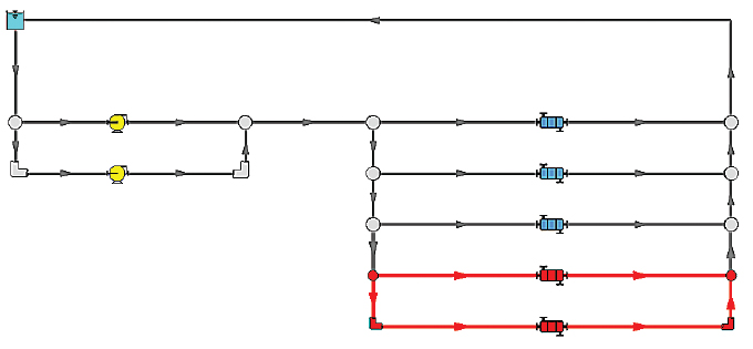
Figure 1 shows a simplified cooling network and its supposed expansion in red. With this we can follow the process a utilities engineer would take to submit an actionable feasibility study. While hypothetical, the principles described can be applied to any system, and analysis expanded to whatever parameters are in question for a specific case.
In the beginning the engineer makes sure the model of the existing system is accurate, comparing to any data they can get, even if it is just the annual flow survey. Then they add the expansion, also ensuring they can justify any assumptions and its subsequent accuracy. They check results to see how parameters, such as pump performance, flows, and velocities, have changed.
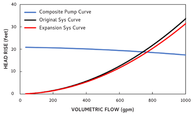
Initially, they look at the pumps’ shifted operating points. It turns out there is less total system resistance from opening more parallel paths. This shallows the system curve, making the pump supply more flow. However, the engineer finds operation really did not shift much, avoiding the concern of running the pump out on its curve. Figure 2 compares the two system curves. With the pumps confirmed OK, they can look at each unit to see if flow and velocity requirements are met.
The engineer knows they need velocities above 3 feet per second through the exchangers but wants them no higher than 8 feet per second. Enough speed is needed to avoid any sedimentation or fouling, but too high of velocities indicates system inefficiencies and can cause other damage. If both goals can be met, that is ideal. The expansion without any modifications indicates the most remote exchanger (bottom line) has a velocity under 3 feet per second. He also notices the least remote (top line) exchanger has a healthy margin with velocity at 6 feet per second and has flow above what’s necessary.
THREE SOLUTIONS
They then test three hypothetical solutions: (1) larger pumps to supply more total flow, (2) smaller pipes in the top line to increase local resistance, and (3) throttling valve in the top line to similarly increase resistance. All three solutions are found to work, which alone is valuable insight, but only one will dubbed the optimal.
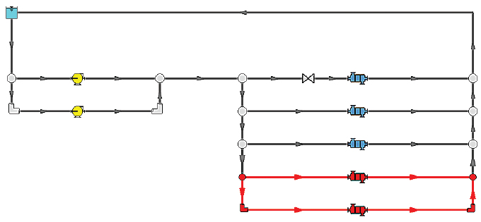
While larger pumps can do the job, it supplies the top exchanger with excessive velocity and flow and is capital intensive. The second option to replace the top exchanger’s piping is effective at redirecting flow without changing pump operation much. Dropping the diameter a couple inches does the trick, but that solution is still expensive and undesired if the pipes still have a lot of life left. The final, throttling valve solution similarly redirects flow to the other exchangers. This looks like the best solution—cheap, simple, and effective—assuming they can plan appropriately for installation. The model also reveals the proper valve size (flow coefficient, Cv) to get the job done. See figure 3 for the results.
Now the engineer can give recommendations to management on approaching the expansion. Of course, there are many other scenarios to test, and more parameters to consider than this simplified example, but the main point stands. Modeling software invaluably helps process engineers make faster and smarter decisions.
Utilities and offsites is a special division of processing plants, wherein engineers of old did not have the insight to make confident recommendations. Software changes the landscape by allowing them to understand their systems and to experiment for the best solution when needs arise. As my colleague put it, “I don’t know how we would have done those expansions without software.”
FOR MORE INFORMATION
Walt Prentice is a business applications engineer at Applied Flow Technology (AFT). Prentice holds a bachelor of science in chemical engineering with a minor in economics from the Colorado School of Mines. At AFT, he supports engineers around the world to troubleshoot their piping and ducting models. For more information, visit www.aft.com.
MODERN PUMPING TODAY, October 2021
Did you enjoy this article?
Subscribe to the FREE Digital Edition of Modern Pumping Today Magazine!