By Heinz P. Bloch
The recent book “Optimized Lubrication, Oil Mist Technology, and Storage Preservation” (see reference 1) delves into issues that were recognized and corrected by best-in-class companies decades ago. Elsewhere, regrettably, certain old pump issues are still not receiving the attention they deserve. Perceptive reliability managers can address the problem by placing reference 1 and similar books in the hands of reliability and technical workforce members. Managers can then ask the staffers to read these texts between today and the employee’s next performance appraisal. An employee could be instructed to point out, and in some cases defend, the differences between “us” and “them.” As the top reliability professional, a reliability manager would thus help staffers understand that reading is one of the essential steps towards professional growth. In the same vein, the staffers’ acquisition of knowledge would enhance the company’s profitability and reliability performance in good times and in bad times.
WHY IS THIS IMPORTANT?
Design improvements to the power end of most types and sizes of process pumps have been primarily neglected in the many years since pump selection largely emphasized initial cost and hydraulic efficiency. However, published hydraulic efficiencies rarely include the additional power demand of bearings, mechanical seals, and shaft couplings. Experience shows that low initial pump cost often comes at the expense of increased maintenance requirements.
Best-in-class pump users specify above-average quality pumps, which often include canned motor pumps from highly experienced manufacturers. While these facts are thoroughly explained in reference 2, the purpose of this two-part article is to outline, in a thumbnail sketch, a few elusive failure causes; each will focus on cost-justified upgrading of API-style pumps.
GREASE VERSUS OIL
Oil has advantages over grease because it removes much more heat than grease. Grease may be better suited to applications where it is desired to confine the lubricant to the bearing. Both oil and grease can be applied in different ways. Grease is normally used in electric motor drivers ranging from fractional horsepower to approximately 500 kW. This is because grease can be readily introduced in small to medium electric motor sizes where motor end caps readily accommodate grease. Here, the end cap acts as an external grease replenishment reservoir. Lifetime lubricated bearings are used in pump sizes up to perhaps 10 kW. In lifetime lubrication the bearings are pre-filled with grease and this grease is confined within seals that are press-fitted in the bearing’s outer ring. Lifetime lubrication implies that grease cannot be replenished and that the bearing operates with this self-contained miniature reservoir until the grease is spent.
However, as pump bearing size and shaft speed reach higher values, oil often represents an overall cost advantage when contrasted against the total cost of frequent grease replenishment and its typically higher failure frequencies.
THE CASE FOR OIL MIST LUBRICATION OF PUMP AND MOTOR BEARINGS
The merits of plant-wide oil mist lubrication for process pumps and their electric motor drivers have been documented in dozens of books and over one hundred articles since 1960. Oil mist is an aerosol; it is applied as a thin film and causes bearings to operate cooler that those operating with conventional liquid oil application. The newer oil mist systems are fully self-contained; little, if any oil escapes from a closed system into the surrounding atmosphere.
While plant-wide oil mist systems lubricate running pumps and fully protect standby machines at best-in-class (BiC) facilities, the electric motor drivers at BiCs are also connected to the oil mist supply headers. Substantial cost savings are realized when periodic re-greasing is thus eliminated. Payback for plant-wide oil mist systems often ranges from one to slightly over two years.
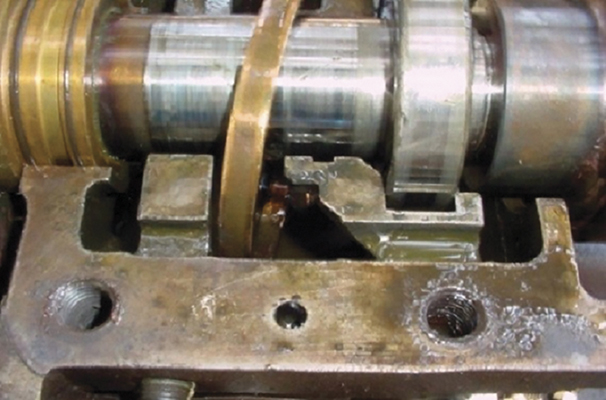
of the bearing’s housing and suffers abrasive damage.
WHY OIL RINGS ARE NOT BEST-AVAILABLE TECHNOLOGY
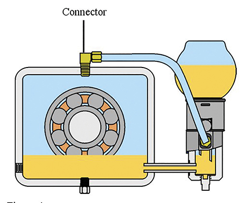
An oil ring is shown in figure 1. As it meanders back-and-forth on the shaft, it inevitably bounces off the surrounding stationary parts. An oil ring then leaves behind miniscule slivers of brass or bronze, which render the oil unserviceable and cause bearings to fail prematurely (see reference 2).
Whenever a plant uses outdated oil ring technology, these oil rings should at least be custom designed for the viscosity of the lubricant. Allowing deviations from acceptable lubricating oil viscosity, operating with shaft alignment other than perfectly horizontal, or installing oil rings with out-of-range dimensional concentricity (i.e., slightly oval instead of perfectly round) will reduce satisfactory operating times. When three or four seemingly minor deviations combine, serious failure events will become frequent. Frequent pump fires have been documented for decades, and the next one may be the one a plant will come to regret. Moreover, we have been observers in court proceedings where a plaintiff’s lawyer explained to the jury that defendant(s) did not use best-available technology. Whichever party neglected to specify or procure best available technology will find it difficult to prevail in court.
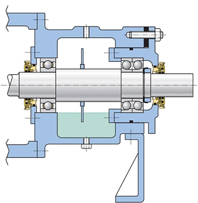
A good pump specification will contain a clause requiring oil rings to be stress-relieved (annealed) before finish machining. Bearing housings must incorporate bearings placed in the cartridge shown in figure 2 for the simple reason that this will allow access and insertion of the type of fixed-on-shaft flinger disc shown here. Nevertheless, flinger disc designs must follow sound engineering practices. A particular design usually satisfies only a narrow range of intended duties; discs must be securely fastened to pump shafts. Experienced European manufacturers often offer them as standard components. However, flinger discs will allow pump shafts to deviate considerably from precise horizontality. They either make shallow contact with the oil level or, more often, the flinger discs are partially immersed in the bearing housing’s oil sump. The design intent of the former is to avoid a layer of hot oil floating on top of the oil, whereas the latter is supposed to pick up and fling lubricating oil into the bearings (see reference 1).
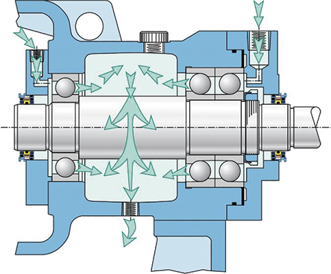
Advanced lube applications include jet oil spray, also called oil jet lubrication, as seen in figure 3. The same illustration depicts only one of several possible ways of applying oil mist. Either a jet of liquid oil or a whiff of atomized oil (oil mist) introduced about 0.37-0.40 inches (10 millimeters) from the bearing’s rotating cage will overcome the fan effect or windage of inclined angular contact cages. It also provides an oil film of optimum thickness for lubrication and heat removal, regardless of bearing orientation (see reference 2).
CONSTANT LEVEL LUBRICATORS
Usually, the simplest oil application method involves using one of the many constant level lubricators. A widely used version is shown in figure 4. However, side mounted constant level lubricators or oilers are unidirectional. For proper operation, an oiler should be mounted on the up-arrow side of a bearing housing. With the counterclockwise shaft rotation indicated in figure 4, the oiler shown on the left side should be removed to reduce the risk of air being ingested.
Unless the lubricator is properly mounted on the up-arrow side of the shaft’s rotation, there will be an increased risk of the oil level lowering as indicated in the pressure versus temperature relationships explained by the laws of physics. If the pressure in a closed bearing housing increases due to a slight temperature increase, the resulting pressure increase will lower the oil level. The oil may suddenly no longer flow into the bearing, the top layer of oil in the sump will quickly overheat and black oil will form. At that point, the bearing will start to fail. Pressure balancing lubricators (see figure 5) are much preferred over the two unbalanced types shown in figure 4.
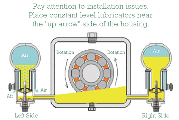
Figure 4: With the counterclockwise shaft rotation indicated here, the oiler shown on the left side should be removed to reduce the risk of air being sucked in. (Source: Trico Corporation)
Caulking is used to seal the external contour where the transparent oiler bulbs in figures 4 and 5 join their cast metal support frames. Since the oiler bulb and its caulking are subjected to numerous swings in ambient temperatures, the caulking will develop micro-cracks. Rainwater runs down on the glass, and capillary action pulls the water into the micro-cracks; water will thus mix with the lube oil in the cast metal support frame. Since we have not seen the resulting contamination described or mentioned in pump manufacturers’ manuals, it is possible that pump manufacturers are simply not aware of this elusive water intrusion path.
WHERE YOUR OWN RELIABILITY ENGINEERS FIT IN
When all is said and done, the owner’s engineers must make a choice: They can either follow the indifferent majority which, occasionally, includes some pump manufacturers. Alternatively, the owner’s reliability professionals can retrieve material wherein unbiased professionals explain the facts, or treasured truth. Our advice for engineers and reliability technicians is to study the facts, understand the science of lubrication (tribology), and then teach others. Whatever implementation routine they choose, it cannot possibly contradict science and must always be backed by common sense. This is a very important admonition for facilities that cling to old anecdotes, misleading anecdotal claims that made the rounds decades ago. Indeed, we occasionally hear out-of-context anecdotes of pump reliability (or unreliability) that should have been discarded thirty or forty years ago.
On the brighter side, we are often pleased when contacted by companies that saw merit in fact-based reliability initiatives. Some quickly became known as best-in-class performers and many never gave up their top rating. There are two examples that illustrate how BiCs did it:
First, we look at the example of a large oil refinery in India which re-examined oil mist technology. They convinced themselves that pure oil mist works flawlessly on hundreds of hot service pumps in oil refineries around the World and, since 1980, has excelled over all other possible lube application methods. The Indian experience can be applied at “Refinery X.” If someone claims that it does not work at “Refinery X,” consider asking what it is that people at “X” are doing different from their best-in-class competitors. In other words, if oil mist works well on hundreds of seemingly identical pumps at ten other refineries elsewhere, the problem at “Refinery X,” where it presumably does not work, must be with one or more of its key employees.
Our second example mirrors the first one. Suppose oil mist, although successfully used on 52,000 electric motors, is opposed by a key staffer at “Chemical Plant Y.” This is a true store; it relates to company “Y.” A staffer at “Y” erroneously claims that oil mist systems cannot provide proper lubrication for the electric motor bearings at “Y,” and that oil mist attacks the motor’s winding insulation. Well, it is perhaps time for top managers at “Y” to ask some serious questions. As a last resort, the managers may have to convince key staffers to read reference 1 and report their findings. If staffers at “Y” persist in clinging to anecdotes, consider pushing for cultural changes. Ask the doubters to explain the consequences of not being attentive to avoidable repairs, high maintenance cost outlays, and below-average plant profitability at “Y.” If all fails, consider reassigning the unteachable to jobs where they cannot impede progress.
A LOOK AHEAD
In the second part of this series, we will take a closer look at oil rings, their role in pump optimization with more detailed excerpts from reference 1, as well as timely recommendations for all results-oriented managers looking to keep their reliability engineers on the path of professional growth.
REFERENCES
Bloch, Heinz P., Don Ehlert, and Fred K. Geitner; “Optimized Equipment, Oil Mist Technology, and Storage Preservation” (2020), Reliabilityweb, Ft. Myers, FL: ISBN 978-1-941872-98-7.
Bloch, Heinz P.; “Fluid Machinery: Life Extension of Pumps, Gas Compressors, and Drivers” (2020), DeGruyter Publishing, Berlin, Germany: ISBN 978-3-11-067413-2.
FOR MORE INFORMATION
Heinz P. Bloch resides in Montgomery, Texas. His professional career commenced in 1962 and included long-term assignments as Exxon Chemical’s regional machinery specialist for the United States. He holds B.S. and M.S. degrees (cum laude) in mechanical engineering from the New Jersey Institute of Technology’s Newark College of Engineering (“NCE”) and was honored as one of ten inaugural inductees into NCE’s “Top 100 Hall of Fame.”
MODERN PUMPING TODAY, August 2020
Did you enjoy this article?
Subscribe to the FREE Digital Edition of Modern Pumping Today Magazine!