By Heinz P. Bloch
For many years, the author maintained that results-oriented managers will put good technical texts in the hands of his reliability engineers and ask them to read these texts between today and the staffer’s next performance appraisal. In time periods when many must work at or from home, these reading assignments may take on added importance. As senior professionals, managers would impress on staffers that reading is better than “re-inventing the wheel” through experimentation. Reading is essential to professional growth. Please consider the following brief excerpts from reference 1 and then ask: Did I know that? Do my employees know it? Why aren’t we upgrading our pumps?
VULNERABILITY OF OIL RINGS
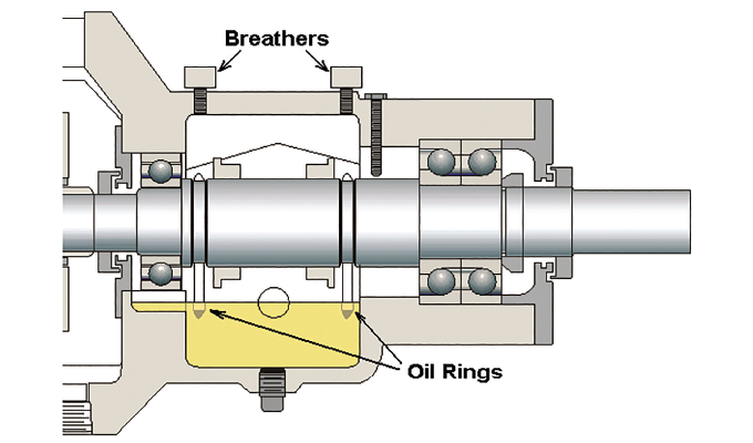
Oil rings are found in many fluid machines and were probably first used in the early nineteenth century. However, they must be installed on a truly horizontal shaft system and not be allowed to contact the housing’s internal surfaces. If (or when) an oil ring jumps out of its groove and gets wedged under a limiter screw (see figure 1, blue arrow), it will often take mere seconds to shred the oil ring and thoroughly contaminate the lube oil. Good designs will not use limiter screws; they will favor limiter discs, shown later. Whenever oil rings are used, depth of immersion and lube oil viscosity must be maintained within acceptable ranges. Ascertaining that the bore eccentricity stays within 0.002 inches is both achievable and strongly recommended.
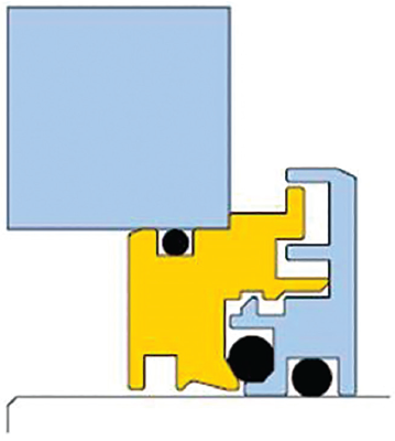
With or without oil rings, oil-related lubrication problems result whenever lubricant is trapped in a dead-end. If no oil return passage (i.e., hole or slot) is provided, a small pool of oil forms and soon overheats. In figure 1, only one oil return slot is shown; it is located below the radial bearing. No bearing housing protector seals are shown in figure 1; however, fitting advanced bearing housing protector seals (ones that incorporate an axially moving O-ring; see figure 2) makes economic sense.
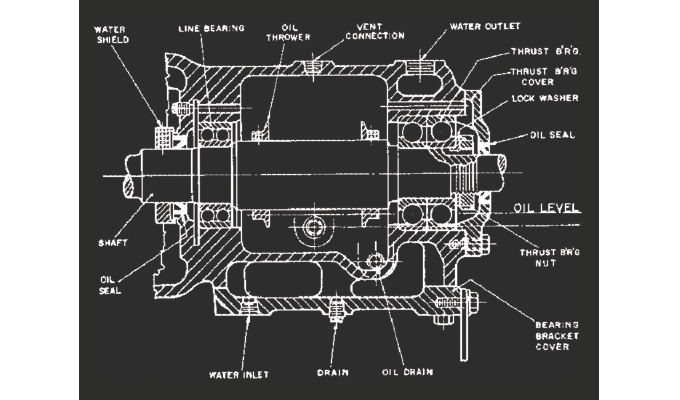
In the 1960s, prudent, highly experienced engineers at a now defunct New Jersey pump company wisely placed a series of pressure equalization holes around each bearing, as shown in figure 3. Without equalization, the oil would often leak from under the lip seals.
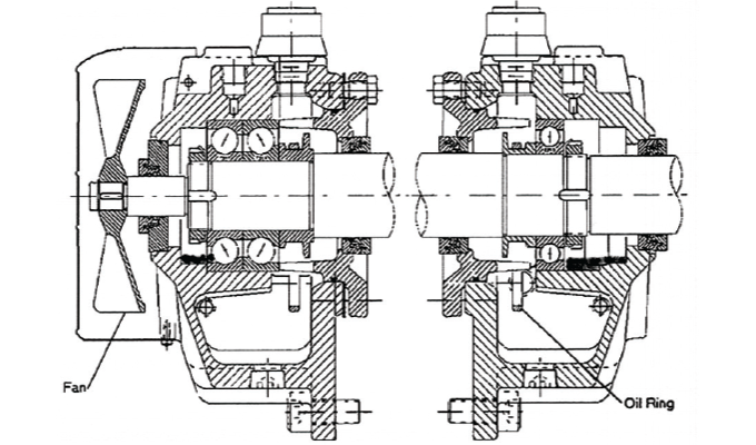
Yet, the “new” bearing housings of the late 1990s, shown in figure 4, show neither the equalization holes nor oil return slots. Sometimes, these holes and slots may not be needed. However, an issue arises if they are needed and, for some unspecified reason, have not been provided on the design drawings. Lack of oil return slots is a reliability risk.
OIL RING ISSUES
If the effects of oil ring malfunctions are communicated to the manufacturer, the inevitable standard answer is that things go well wherever else identical pumps are being used. An alternative claim is often made; vendors have asserted that this is the first-ever complaint and that the pump user must be doing something wrong. The manufacturer may even resent your insistence on upgraded, lower failure risk pumps because upgrading interferes with the manufacturer’s projected spare parts sales or might be viewed as the manufacturer’s admission that better technology is available.
So, who is to be believed? Whose claims represent facts? Is it the recollections of a vendor’s technical director/manager who has never once accepted responsibility? What is known as fact is that no oil return holes are shown on the drawing reproduced in figure 4. What is also known is that the author has measured oil rings with an out-of-roundness of 0.061 inches at a facility in Point Comfort, Texas, and 0.017 inches at a refinery in Corpus Christi, Texas. The widely used Wilcock and Booser text (see reference 2) gives 0.002 inches as the maximum allowable out-of-roundness and explains what might happen when this tolerance is exceeded. Oil ring out-of-roundness is often caused by disregard or even ignorance of the importance of stress-relief annealing as an intermediated step in manufacturing oil rings.
Any issues centering on oil ring deficiencies or balance hole provisions have been solved years ago. Problems can be circumvented by what all bearing manufacturers know: An oil jet sprayed directly at the bearing cage (i.e., ball separator) ranks first in yielding maximum trouble-free bearing life. Oil rings and constant level lubricators are discarded with oil jets or oil mist. Oil mist, applied between a bearing’s housing protector seal and the bearing, and aimed or “directed” to flow through the bearing before reaching the oil sump, is ranked a close second. Among the strengths of these two highest ranked application methods is the fact that shaft orientation does not, in any way, interfere with getting clean oil into the bearing.
The same cannot be said for oil rings, which, of course, are highly orientation sensitive. Unless the shaft on which they ride is perfectly horizontal, oil rings will travel downhill. Unless the oil rings are immersed in oil to the correct depth and the oil has the right viscosity, they may not perform as intended. Oil rings will not perform properly if roundness and bore concentricity are outside the limits of 0.002 inches called for in reference 2. To maintain acceptable roundness and concentricity, reliable oil rings are fabricated with an intermediate stress relief step after rough machining. Only then are the oil rings machined to an engineered final dimension.
OIL RING CROSS SECTIONS AND OIL GALLERIES
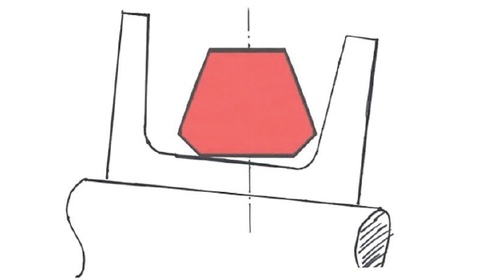
In a series of rigorous tests, a pump manufacturer established that oil rings with cross sections resembling the mirror image trapezoids in figure 5 may better tolerate wave motion on ships. The trapezoidal oil rings should be retained on tapered flank ring carriers from which they (hopefully) will fling oil into oil galleries.
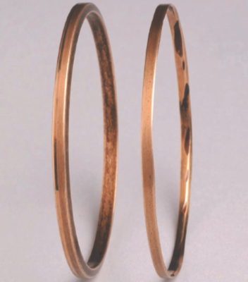
But, again, the user’s pumps may incorporate the traditional flat oil rings. If the facility and its reliability engineers are happy with them, they may simply stay the course. If not, it is time to write better specifications for vendors and insist on specification compliance by the various bidders. Meanwhile, user plants might consider putting relevant oil ring dimensional details into their computerized maintenance management system (CMMS). Additionally, personnel should measure and record the oil ring width and oil ring concentricity, as installed. The same two measurements, width and concentricity, should be repeated and documented when doing repairs. At times, the difference between these measurements is evident to the naked eye, as seen in figure 6. Note how the chamfers are worn on one of the two oil rings. The difference ended up as abrasion product; it contaminated the oil and caused premature failure of the bearings.
To what extent these documented events prompted searching for new oil ring contours is not known. What is known is that considerable research was done by a major pump manufacturer and that:
- Certain plastic materials were proposed for oil rings instead of brass or bronze;
- Plastic oil rings were retrofitted in a pump user’s plant, but did not solve the issue of black oil formation;
- A research report recommended ISO VG 46 or ISO VG 52 instead of the customary ISO VG 32 lubricants; however,
- The researchers did not comment on viscosity indices. Industry uses a viscosity index to quantify how much an oil will thicken when it is being cooled and how much easier it will flow when the oil’s temperature is being increased over a prevailing standard temperature. Unless the viscosity index is taken into account, it will be pointless to call for tweaking the viscosity of a lubricant.
CONSIDER OIL APPLICATION METHODS OTHER THAN OIL RINGS
Earlier in this article we stated that oil sprayed into rolling element bearings is the most desirable application method and that oil mist is a close second. We believe that pump reliability can be improved by either of these two approaches and that reliability-focused users should specify these options. Both are explained in greater detail in reference 1.u
REFERENCES
- Bloch, Heinz P., Don Ehlert, and Fred K. Geitner; “Optimized Equipment, Oil Mist Technology, and Storage Preservation” (2020), Reliabilityweb, Ft. Myers, FL: ISBN 978-1-941872-98-7.
- Wilcock, Donald F., and E.R. Booser; Bearing Design and Application” (1957), McGraw-Hill, New York, NY 10121.
FOR MORE INFORMATION
Heinz P. Bloch resides in Montgomery, Texas. His professional career commenced in 1962 and included long-term assignments as Exxon Chemical’s regional machinery specialist for the United States. He holds B.S. and M.S. degrees (cum laude) in mechanical engineering from the New Jersey Institute of Technology’s Newark College of Engineering (“NCE”) and was honored as one of ten inaugural inductees into NCE’s “Top 100 Hall of Fame.”
MODERN PUMPING TODAY, September 2020
Did you enjoy this article?
Subscribe to the FREE Digital Edition of Modern Pumping Today Magazine!