According to major bearing manufacturers such as SKF, an estimated 63 percent of premature bearing failures can be directly or indirectly attributed to lubrication. Figure 1 includes the obvious incorrect or lack of lubrication which equates to 11 percent but perhaps the biggest contributor to bearing failure, contamination. According to the data represented in figure 1, 47 percent of premature failures are due to lubricant contamination, though it could be argued that a large percentage of those failures attributed to corrosion are also contamination related since water and other process chemicals are a significant and obvious contributor to corrosive failures.
Put simply, whether you include corrosion as a contamination induced failure mode, close to 50 percent of all failures are contamination related, making this the largest contributing factor to pump failures.
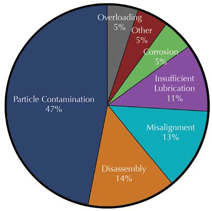
Figure 1: Causes of bearing failure (Ref: SKF)
LUBRICANT CONTAMINATION CONTROL IN PROCESS EQUIPMENT
In pumps and other process equipment, preventing contaminants from entering the lubricant requires a holistic focus on all major sources of ingression.
These include:
- Shaft seals
- The fill port and/or breather port
- Contaminants introduced during routine maintenance
All three must be addressed in order to develop a comprehensive contamination control strategy. But before we can introduce solutions for controlling contaminants, it’s important to understand what level of contamination exclusion we should be aiming for.
HOW MUCH IS TOO MUCH?
Water
Water in oil causes a number of negative effects including loss of film strength, rust and corrosion, and premature lubricant degradation. Because of this, water levels should be kept below the oil’s saturation point at all operating temperatures, meaning that any water that is present is dissolved in the oil rather than free or emulsified. In practical terms, this means keeping water levels below 100 to 200 parts per million (0.01-0.02 percent v/v) depending on the type of fluid and operating temperatures. For stop-start applications, targets should be set even lower since an oil’s saturation point is temperature dependent, meaning water will have a tendency to come out of solution when the pump shuts down and the oil cools. Figure 2 illustrates the impact that free and emulsified water has on plain and rolling element bearings.
Particles
Particle contamination is typically measured in lubricating oils according to the ISO 4406:99 standard. For those unfamiliar with this rating, there are a number of good articles available online that explain the concept. Using this standard, the optimum particle cleanliness target for pumps will vary based on criticality, but should typically be set in the ISO 18/16/13 (c) to 15/13/10 (c) range. It’s important to note that this standard reports particles that are in the 4-14 micron range – too small to see with the naked eye and similar in size to red blood cells or bacteria! The life expectancy of bearings and other oil wetted components relative to the level of particle contamination is shown in figure 3.
To meet these targets for particles and moisture, we’re going to need to address all three sources of contaminant ingression: seals, fill/breather ports and introduced contaminants.
CONTAMINATION EXCLUSION: SEALS
Particularly in process industries where airborne contamination is unavoidable; shaft seals become a major source for contaminant ingression. For pumps that have little more than a lip seal, preventing contaminants from entering through the seal can be a major problem. For this reason, mechanical seals have become the preferred method for most process pumps. But although most mechanical seals do a good job of excluding contaminants, they often have a negative effect: sealing contaminant—particularly moisture—inside the pump housing.
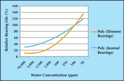
Figure 2: Impact of water on plain and element bearings
CONTAMINATION EXCLUSION: BREATHER/FILL PORTS
Perhaps the most significant source of contamination ingress is through the breather/fill port. Often, this is little more than a bent piece of piping (Figure 4), something that will do little to nothing to keep out moisture or bacteria sized particles! In some instances, particularly where mechanicals seals are in use, there is a tendency to replace the breather with a sealed pipe plug. While this will certainly exclude most contaminants from entering through the fill port, a pump will always find a way to breathe, whether it’s through a seal or other port. In this case, the pipe plug has the opposite result to the desired outcome, sealing in contaminants, particularly moisture.
A far better approach to controlling contaminants is to use a desiccant breather. Desiccant breathers contain two types of contamination control media: silica gel to remove moisture and a particle removing membrane capable of eliminating particles down to 1 micron. There are three basic designs of desiccant breathers: free breathing, vented and expansion chamber.
Free-Breathing Desiccant Breathers
Original designs of desiccant breathers used a free breathing concept (see figure 5) which is conceptually very simple. As the air within the bearing housing expands with increasing temperature, air passes through a central standpipe, through the particle media and silica gel bed, and is exhausted to atmosphere. Conversely, when temperatures decrease and the pump needs to breathe air, the ingressed air passes through a 3 micron absolute particle media, through a silica gel bed, and through a second particle media insuring that both particles and moisture cannot enter the bearing housing through the breather/fill port.
Vented Desiccant Breathers
One of the challenges and long standing criticism of free-breathing desiccant breathers is their replacement cycle. Desiccant breathers need to be replaced when the silica gel media changes from blue to pink; an indicator that the silica gel is saturated with moisture. With a free breathing design, the silica gel is constantly in contact with the outside atmosphere meaning that even if the pump is not actively breathing, the silica gel is slowly adsorbing water vapor. As a result, free-breathing breathers may only last a few weeks in a high humidity environment.
To solve this problem, vented breathers have been developed. These breathers include two sets of opposed vent valves. The valves have a very low cracking pressure set at 0.23 psid. Under steady state conditions (i.e. the system is not breathing in or out) the valves are closed. However, if the pump cools down and needs to breathe in, two of the valves open to allow air to enter; passing through the same 3 micron particle media and silica gel bed found in free-breathing breathers. Conversely, if the pump heats up and needs to exhale, the opposing set of valves open to relieve pressure within the head space. Ideal for use in high humidity environments with minimal volumetric cycling due to temperatures changes within the bearing housing, vented breathers can last 10 to 20 times as long as free breathing breathers depending on the application.
Expansion Chamber Breathers
In some instances where small volumetric exchanges occur frequently, a better option is to use an expansion chamber style breather. Similar in design to a vented breather, a hybrid expansion chamber breather has similar check valves to the vented design, but with the addition of a diaphragm that expands and contracts to equalize pressures with small variations in temperature. The advantage of having the diaphragm and silica gel versus just a simple diaphragm is the ability of the silica gel to adsorb moisture from the headspace. Without the silica gel, a diaphragm would have the reverse effect, sealing water vapor within the housing.
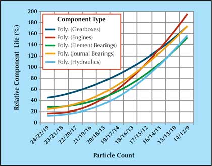
Figure 3: Impact of particle contamination on oil-wetted component life
CONTAMINATION EXCLUSION: INTRODUCED CONTAMINANTS
The last source of contamination ingress comes from contaminants introduced during routine maintenance tasks such as level checks, oil changes and top-offs. As much as possible all equipment should remain sealed throughout its life. To do this, the pump should be equipped with quick-connects, external oil level gauges and permanently mounted oil sample valves. A number of devices are available that allow for any pump to be quickly and easily modified to facilitate almost complete isolation of the oil sump from the ambient environment during normal and routine operations and maintenance.
With the pump modified, basic lubrication tasks including oil changes, oil top-offs, level checks and visual oil analysis inspections can all be accomplished without exposing the lubricant to external contaminants.
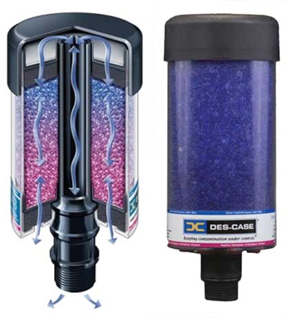
Figure 5: Air flow path through a free-breathing desiccant breather
SUMMARY
With as many as 50 to 70 percent of all failures related to lubricant contamination, it’s little wonder that just a small focus on improving the condition of the lubricant can have a dramatic impact on bearing life. Simple, inexpensive changes such as using desiccant breathers and minor housing modifications can have a profound impact on reliability and lifecycle cost.
About the Author
Mark Barnes is vice president–reliability services for Des Case Corporation, who specializes in contamination control products for industrial lubricants. Headquartered near Nashville, Tennessee, Des Case markets an entire line of products designed to help companies make their equipment investments last longer. For more information, visit www.descase.com.
MODERN PUMPING TODAY, November 2014
Did you enjoy this article?
Subscribe to the FREE Digital Edition of Modern Pumping Today Magazine!