Ferdinand Porsche is best known today for the sports cars that bear his name, but, among other engineering breakthroughs, he also built the first hybrid automobile, which he displayed at the Paris World’s Fair in 1900. Now it was nearly a century before Toyota released the Prius and other car manufacturers (including Porsche) followed suit with their hybrid models, but in the meantime hybrid drive technologies had caught on in a large number of other industries including marine propulsion, trains, pipeline compression, and steel plants.
CLUTCHED HYBRID SYSTEMS
Some hybrid designs, such as those used in trains and ships, use fossil or nuclear fuel to power an engine that drives a generator, and the electricity produced then drives the motors. For pumps and compressors, however, a better arrangement is to use clutches to connect both a motor/generator and an engine to the workload. In such a case the operator can then decide whether to run the engine, the motor or both at the same time, depending on the price and availability of fuel and electricity. This approach not only reduces energy costs, but also lowers capital costs, improves reliability and availability, and makes it easier to schedule maintenance.
Currently there are several thousand such clutched hybrid systems in use at power plants, on natural gas pipeline compressors, in marine propulsion systems and at water pumping stations. But the municipal water and sewage treatment industry has lagged behind others with only a few plants so far achieving the benefits of such hybrid systems, mostly due to unfamiliarity with the technology. To remedy that, here is a description of how dual drive systems work and how they can benefit utilities.
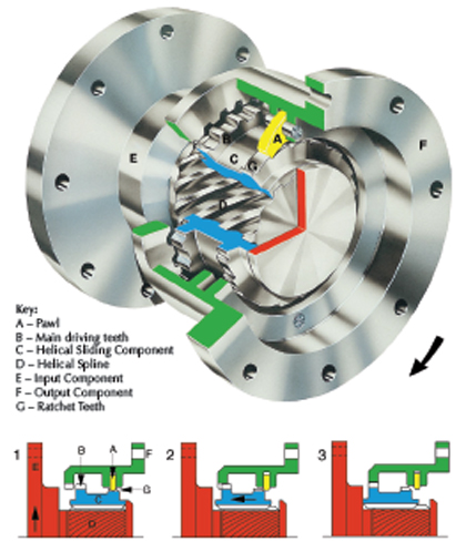
Figure 1: How an SSS clutch works
TYPES OF OVERRUNNING CLUTCHES
The key to making hybrid systems work are the clutches that allow a plant operator to engage or disengage each of the elements of the equipment train, including the engine, motor/generator and the load, whether a pump or a compressor. This allows the components to work independently or in unison so as to achieve the most economical and efficient operation.
A freewheel or overrunning clutch is a one-way clutch that allows the transmission of torque in one direction from one rotating shaft to another. The clutch mechanically engages when the driving shaft speed attempts to overtake the speed of the driven shaft and disengages when the torque reverses on the driving shaft or the driving shaft speed decreases below that of the driven shaft.
The condition of “freewheeling” occurs in most bicycles when the rider stops pedaling and the bicycle coasts. Without a free-wheel, the rear wheel would drive the pedals around. Overrunning clutches are not friction clutches and cannot force the speed of one shaft system to match the other.
LOW POWER OVERRUNNING CLUTCHES
Low power overrunning clutches up to a few hundred horsepower rating include ramp-and-roller and sprag-type clutches. Both of these synchronize and transmit torque by wedging loose parts between inner and outer cylinders within the clutch.
Ramp-and-roller clutches have a series of ramps on the inner cylinder. When the inner cylinder moves in one direction at a speed equal to or greater than that of the outer cylinder, the ramps wedge the rollers against the outer cylinder, transmitting the torque. Sprag clutches use figure-eight shaped rollers called sprags which allow the unit to freely spin in one direction, but when the direction is reversed, wedge between the inner and outer cylinders.
These types of clutches are generally limited to low power services below 3600 revolutions per minute. The clutch components can deform or brinell—particularly under high stress and if there is some accompanying machinery vibration—and are sensitive to shocks, sudden torque overloads and the cleanliness of lubricating oil. That said, they are still well suited for many low-power service applications.
HIGH POWER OVERRUNNING CLUTCHES (GEAR TOOTH TYPE)
For high-horsepower, critical-service applications, an automatic overrunning clutch, such as a Synchro-Self-Shifting (SSS) Overrunning Clutch, is normally utilized. These clutches transmit torque through multiple gear teeth and separate the synchronizing function from the torque carrying components.
With such clutches, small pawls are used to mate with ratchet teeth to align and then shift the clutch teeth into engagement along helical splines (see figure 1). The teeth are engaged automatically at synchronism at any speed from rest to full operating speed. The pawls and ratchets are inactive except during the short engagement process. Once engaged, torque is transmitted through the surface contact of concentric involute shaped teeth. An internal oil dashpot, between the input and output components, cushions the engagement of the clutch.
High power overrunning clutches can be completely supported by the shafting and engineered to either act as a solid coupling when engaged and transmitting torque or designed to accept axial and offset misalignment. Alternatively, overrunning clutches can be mounted in an oil-tight housing which can be foot mounted or connected to the casing of the driving or driven machine.
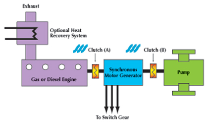
Figure 2: Schematic of dual-driven pump
DUAL-DRIVEN TRAINS
A dual-driven equipment train with an overrunning clutch enables one driver to be disconnected from the train and stopped, while the second driver continues to power the driven machine. It also allows the driven equipment to begin operation with one of the drivers when the second driver is not available due to process, maintenance or other constraints, and to start and engage this driver with the already running train when the constraint no longer exists.
For example, there are over a hundred dual-driven compressors used in natural gas pipeline applications with powers ranging from 1000 to 7000 horsepower. These trains use electric motors and gas engines as the dual drivers. The dual drivers allow the choice of power source depending on the real time cost advantages of one power source versus the other. Engine maintenance can take place while the train continues to operate using the motor driver.
With two clutches in place, the drive train can also be used as an electrical generating source. When compression is not required, the engine can disconnect from the compressor and drive only the motor/generator, exporting power to the grid. Or with both clutches engaged and the power requirement of the compressor less than the engine rating, the extra power can be used to generate very efficient power for export since the full load engine fuel rate is significantly better than the part load rate.
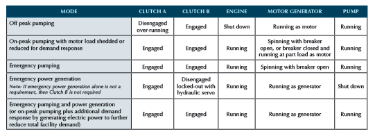
Figure 3: Operating modes of dual-driven pumps
DUAL-DRIVEN EQUIPMENT IN WATER WORKS
This same dual-drive concept could be applied to both compressors and pumps used by the water works industry.
First, let’s look at compressors. In a sewage treatment plant there is typically an engine burning digester gas as fuel that drives a generator and on a separate foundation there is a motor that drives an air compressor supplying the oxygen required by the digester. Using the dual drive concept, the engine, compressor and motor/generator would be combined in one train on a single foundation thus requiring only one motor/generator versus a separate motor and generator in a conventional arrangement. In addition, only one set of switchgear and cabling is required.
Pumps would use a different dual drive configuration. Many pumping stations, both water and wastewater, require standby power to provide pumping during electric power disruptions. Often this is handled by installing an engine-driven pump alongside a motor driven pump, using the engine-driven pump when electric power is not available. This means that the investment for the engine driven pump (engine, pump, foundation, piping, etc.) is rarely used.
In other cases a standby generator set is installed to operate the electric driven pump during power outages. In this case the engine must be sized considerably larger in power than the pump being driven by the generator in order to provide the torque required during the acceleration of the motor driven pump. The generator, which is very similar to the pump motor, needs its own set of switchgear and cabling.
By dual driving the pump with both an engine and motor as shown in figure 2, only a single motor/generator is required with only one set of switchgear and cabling. In addition the engine size is reduced considerably when direct driving the pump. Only one foundation is required. Total footprint is reduced. During a power outage the engine starts and the clutch automatically engages driving the pump through the motor with the motor breaker open. Using a transfer switch, and selecting a synchronous motor (rather than an induction type), the motor operates as a generator to provide station power.
METHODS OF OPERATION
Using a dual-drive configuration for pumps and compressors gives utilities greater flexibility in operating their equipment to minimize costs and improve reliability. Here are five different scenarios that can be used for pump operations, and similar options can be used with compressors. These modes of operation are summarized in figure 3.
Off-Peak Pumping
During off peak hours when electricity prices are low, the engine is shut down and the clutch between the engine and motor generator is disengaged. The motor is using power from the grid to run the pump.
On-Peak with Load Shedding
In many areas electric utilities or grid operators have demand response programs offering as much as $100,000 per year to shed 1000 kilowatt of load a few times a year. Or the utility will charge much higher rates during peak demand periods, making it more economical to use the engine than to purchase electricity. In either case, the engine would be started and used to spin the motor and the pump. Depending on the economics, the breaker would be open with the engine providing all the power, or the motor could be drawing a reduced amount of electricity from the grid to supplement what the engine was providing.
Emergency Pumping
When electricity is not available, the engine will kick in and keep the pump running. The motor will be spinning, but will not be drawing or generating any current.
Emergency Power Generation
There may be emergency scenarios where pumping is not needed, but electricity is. In such a case, the clutch between the motor and the pump is disengaged. The engine drives the motor generator and with the breakers open so it can provide electricity.
Emergency Pumping and Power Generation
In this case, both clutches are engaged, with the engine providing the torque necessary to run the pump and to generate electricity.
In addition to the flexibility offered by these five operating modes, only dual-drive gives engineers the opportunity to shut down either their engine or their motor for maintenance, without interrupting service.
_______________________________________________________________________
ABOUT THE AUTHOR
Morgan Hendry is the president of SSS Clutch. Since its formation more than forty years ago SSS has concentrated solely on the marketing, development and production of SSS Clutches, primarily for high power and high speed applications. For more information, visit www.sssclutch.com.
_______________________________________________________________________
MODERN PUMPING TODAY, September 2013
Did you enjoy this article?
Subscribe to the FREE Digital Edition of Modern Pumping Today Magazine!