METHODS OF OIL APPLICATION
The traditional oil sump was depicted, in figure 5 (see earlier Part 2 of this series, “Insist on Better Pumps,” Modern Pumping Today, February 2013: 30), with the lubricant reaching to about the center of the lowermost bearing elements. This arrangement works well at low shaft surface velocities. To gain reliability advantages, synthetic lubricants, oil mist application (called “oil fog” in some languages), and liquid-oil jets (also known as “oil spray”) are often used. Oil jets are well described in references 1 through 6 and should not be confused with oil mist. But circulating systems also merit consideration in certain high-load or very large pumping services. Generally speaking, circulating systems are selected for large pumps utilizing sleeve bearings. In these systems, the oil can be passed through a heat exchanger before being returned to the bearing. However, regardless of lube application method on rolling element bearings, cooling will not be needed as long as high-grade mineral or synthetic lubricants are utilized (see reference 3). High-performance mineral oils developed around 2012 are deliberately mentioned here.

Irrespective of base stock and oil formulation, the required lubricant viscosity is a function of bearing diameter and shaft speed. Technical reasons are described in numerous books and articles, among them references 7 and 8. Most process pump bearings will reach long operating lives if the oil viscosity (at a particular operating temperature) is maintained in a range from 13 to 20 cSt (see references 3 and 7). It should be noted that whenever oil rings are used to “lift” the oil from sump to bearings, the need to maintain a narrow range of viscosities takes on added importance. In the special case of the same bearing housing containing both rolling element and sliding bearings, it will be prudent to address the implications of (some) oil rings not being able to function optimally in the higher viscosity (ISO Grade 68) lubricant that’s often chosen for rolling element bearings. The oil ring may have been designed to cater to sleeve bearings, which normally need a lower viscosity lubricant, but VG 32 mineral oils are rarely a best choice for rolling element bearings in pumps. A high performance synthetic VG 32 will often succeed as the most suitable selection for different bearing styles sharing the same housing.
To restate the above: Oil overheating must be avoided, especially so on many pumps operating at 3000 or 3600 revolutions per minute with oil reaching the center of the lowermost bearing ball or roller. Because the “plowing effect” of rolling elements in a flooded sump produces frictional power loss and heat, an oil level below that indicated in figure 5 is often chosen and provisions are made to “lift” the oil. A widely accepted empirical rule calls for lower oil levels and “lifting” whenever DN is greater than 6000 (in this expression D equals shaft diameter in inches, and N is the shaft revolutions per minute). Another, separately derived empirical rule, allows shaft peripheral velocities no higher than 2000 fpm in bearing housings where the oil sump level is set to reach the center of the lowermost rolling element.
In oil mist lubrication systems it is generally understood that with shaft surface velocities in excess of 2000 fpm, windage effects are opposing the flow of oil mist. As this is being observed, uninformed or baffled oil mist users have, in some cases, reverted back to conventional oil lubrication. In sharp contrast, reliability-focused users have, for many decades, installed directed oil mist reclassifiers to overcome windage at greater than 2000 fpm. The mist dispensing opening in these reclassifiers is located approximately 0.2 to 0.4 inches (5 to 10 millimeters) from the rolling elements. Thousands of these have been supplied and used with total success. This information is available from dozens of texts and articles (including references 3 through 6).
Again, once the shaft peripheral velocity exceeds 2000 fpm, the oil level should be no higher than a horizontal line tangent to the lowermost bearing periphery. This means there should be no contacting of the oil level with any part of a rolling element and oil “lifting” is needed. Assume that figures 3 and 6 represent situations where DN is greater than 6000. Therefore, and because initial cost was to be minimized, either oil rings (figure 3) or shaft-mounted flinger discs (figure 6) were chosen. Both arrangements are available to lift the oil, or to somehow get the oil into the bearing by creating a random spray.
TWO DIFFERENT DN-RULES EXPLAINED
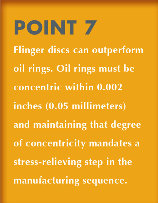
When determining oil level settings, either of two empirical rules could be applied. To illustrate Rule 1, consider that a 2-inch bore bearing at 3600 rpm, with its DN value of 7200, would operate in the risky or ring instability-prone zone, whereas equipment with a 3-inch bore bearing operating at 1800 rpm (DN = 5400) might use oil rings without undue risk of ring instability. In another example, using Rule 2, a 3-inch (76.2 millimeter) diameter bearing bore at 3600 rpm would operate with a shaft peripheral velocity of (πD/12)(3600) = 2827 fpm (approximately 14.4 meters per second), which would disqualify oil rings from being considered for highly reliable pumps. The fact that a pump manufacturer can point to satisfactory test stand experience at higher peripheral velocities is readily acknowledged, but field situations represent the “real world” where shaft horizontality and oil viscosity, depth of oil ring immersion, bore finish and out-of-roundness are rarely perfect. We can thus opt for using either the DN is less than 6000 or the surface velocity less than 2000 fpm “real-world” rules-of-thumb.
Either way, the vendor’s test stand experience is of academic interest at best. Pump manufacturers test under near-ideal conditions of shaft horizontality, oil ring concentricity and immersion, oil level and lubricant viscosity. As users we might ask ourselves how often we have seen non-round oil rings, or rings that have shaft radius wear marks (from shaft fillet radii) on one side of the ring. If the answer is “never,” perhaps another look will be warranted. For the reliability-focused, the wide-ranging field experience that led to these two rules-of-thumb will govern over all else.
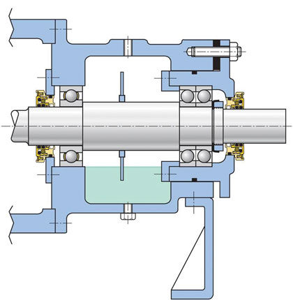
The cartridge approach shown in figure 6 has been in use for an estimated fifty or sixty years on thousands of open-impeller ANSI pumps because it facilitates impeller position adjustment in the axial direction. The same cartridge approach may be needed to dimensionally accommodate flinger discs (figure 6) instead of vulnerable oil rings (figure 7). Of course, cartridge-mounted bearings are a cost-adder and you may hear claims that the benefit-to-cost-ratio will not justify upgrading to cartridges. However, with the average API pump repair costing slightly over $10,200 at a Texas refinery and $11,000 at a refinery in Mississippi, we might be surprised at the payback multiplier. Even a single avoided failure over the thirty-year total life of a pump will probably pay for it.
The quoted repair cost numbers reflect what needs to be considered in a pump repair cost calculation: Direct labor, direct materials, employee benefits at roughly 50 percent of direct labor, refinery administration and services costs at close to 10 percent of direct labor, mechanical-technical service personnel overhead costs amounting to approximately 115 percent of direct labor, and materials procurement costs from 7 to 8 percent of materials outlay (see reference 4). By disregarding the true cost of failures, some professed experts are actually impeding progress towards better pumps.
THE TROUBLE WITH OIL RINGS AND CONSTANT LEVEL LUBRICATORS
Issues with oil rings are found in the works of Heshmat, Wilcock, and Booser, and Leonardo Urbiola (Texas A&M). In a website post in September 2012, the Malaysian equivalent of OSHA alerted us to catastrophic failures brought on by oil rings. All of these sources observed problems with oil rings, although an industry source opined (in 2011) that “ring lubrication is an accepted practice and it would take user consensus to damn it.” Here, it seems that this pump manufacturer’s innovation is driven by consensus. What a pity—like somebody forgot to tell the Wright Brothers to wait.
We just ask you to keep in mind that this tutorial is for the reliability-focused. Nothing will convince those who accept without questioning dozens of repeat failures of centrifugal pumps at their plants. Illustrations of failed oil rings are available and studies have shown them unreliable under less than perfect field conditions. Work done by Heshmat and material contained in a widely accepted bearing and lubrication handbook (see reference 9) recommend oil ring concentricity within 0.002 inches (0.05 millimeters). However, recent shop measurements at a pump user’s site in Texas proved that some oil rings exceeded the maximum allowable out-of-roundness tolerances by a factor of 30.
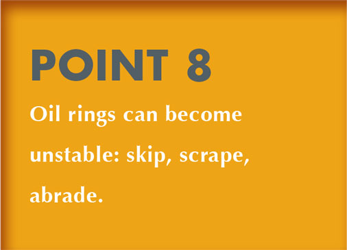
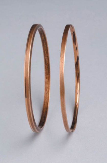
Experience shows that oil rings are rarely the most dependable or least-risk means of lubricant application. They tend to skip around and even abrade (figure 7) unless the shaft system is truly horizontal, unless ring immersion in the lubricant is just right, and unless ring eccentricity, surface finish, and oil viscosity are within tolerance. Taken together, these parameters are not usually found within close limits in actual operating plants (see references 3 and 4).
Reliability-focused purchasers often specify and select pumps with flinger discs. Although sometimes used in slow speed equipment to merely prevent temperature stratification of the oil (see figure 5), larger diameter flinger discs (figure 6) serve as efficient (non-pressurized) oil distributors at moderate speeds. Of course, the proper flinger disc diameter must be chosen and solid steel flinger discs should be preferred over plastic materials. Insufficient lubricant application results if the diameter is too small to dip into the lubricant; conversely, high operating temperatures can be caused if the disc diameter is much too large or if no thought was given to its overall geometry. Flexible flinger discs have been used to enable insertion in some “reduced cost” designs, that is, configurations where the bearing housing bore diameter is smaller than the flinger disc diameter. As was brought out earlier, to accommodate the preferred solid steel flinger discs, bearings must be cartridge-mounted (figure 6). Using a cartridge design, the effective bearing housing bore (that is, the cartridge diameter) is made large enough for passage of a steel flinger disc of appropriate diameter. We know of many attempts to get around the use of oil rings; roll pins inserted transversely in pump shafts (see reference 4, page 251) and flexible (plastic) flinger discs have brought mixed results and marginal improvement at best. Cheap discs pushed on the shaft became a source of failure and were disallowed by API-610 about ten years ago. Cheap plastics and disc configurations chosen without the benefit of sound engineering practices have also not been sufficiently reliable. In all, we should never lose sight of the charter and mission of reliability professionals. We believe their goals should be to work in harmony with basic science and to achieve high pump reliability and availability.
We estimate the incremental cost (comprising material, labor, CNC production machining processes) of an average-size (30 horsepower) process pump with cartridge-mounted bearings at $300. The value of even a single avoided failure was earlier shown to be over $10,000 and the benefit-to-cost ratio would thus exceed 33-to-1. The shortcomings of oil rings were known in the 1970s. A then well-known pump manufacturer claimed superior-to-the-competition products. This manufacturer’s literature pointed to an “anti-friction oil thrower [that is, a flinger disc], ensuring positive lubrication to eliminate the problems associated with oil rings” (see reference 4).
A WELL KNOWN PROBLEM
About two decades later, in 1999, at least one major pump manufacturer saw fit to examine the situation more closely. In a comprehensive paper the manufacturer described remedial actions that included more closely controlled oil viscosity and oil rings made of high performance polymers (see reference 10). However, the problem did not go away. Users in Canada reported that black oil and other repeat failures persisted, even after adopting non-metallic oil rings. Black oil, however, can easily be traced to one of two origins. A simple analysis will point to either overheated oil (that is, carbon) or will detect slivers of elastomeric “dynamic” O-ring material from components that operate too close to sharp-edged O-ring grooves.
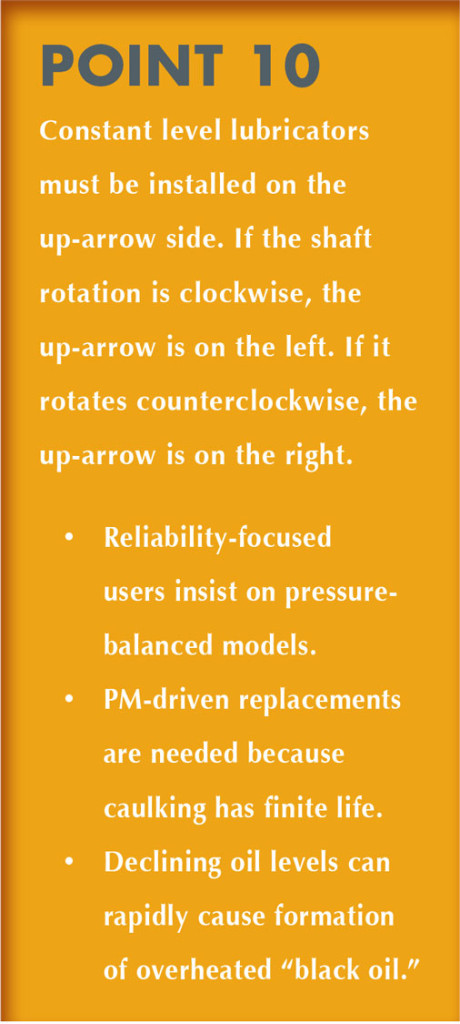
Furthermore, in an advertisement appearing in the 1970s, we see “anti-friction oil thrower(s) [that is, flinger discs] ensuring positive lubrication to eliminate the problems associated with oil rings.” Many European-made pumps incorporate flinger discs (“oil throwers”), and so does at least one U.S. manufacturer.The potential malfunction risks of constant level lubricators are more widely known. A number of makes, models and brands are in common use and their “uni-directionality” is described in the manufacturers’ literature. Less well known is that caulking (where transparent bottles meet die-cast metal bases) will, over time, develop stress cracks (fissures). Rain water can then reach the oil via capillary action. Accordingly, bottle-type constant level lubricators are a preventive maintenance item; they should be replaced after four or five years of service.
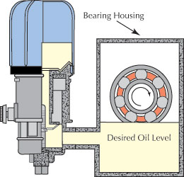
Note also how, in figure 8, the oil level in the bearing housing is no longer reaching the rolling elements. This constant level lubricator lacks pressure balance. Any pressure increase in the space above the liquid oil will drive the oil level down. For a while, the top layer of oil will overheat; carbon will form and black oil will appear in the glass bulb. Increasing temperature in the closed space causes a further pressure increase and the oil level decreases even more. Oil then no longer reaches the rolling elements and another bearing failure is likely.
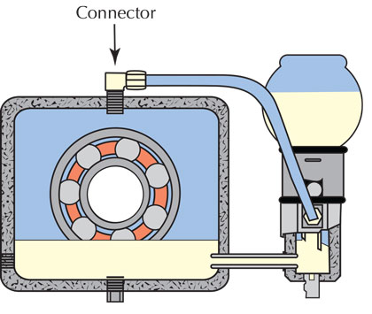
The lubricator in figure 9 is configured for a balance line which ensures that the oil levels in the die-cast lubricator support (or at the edge of the slanted tube shown in this illustration) and in the pump bearing housing are always exposed to the same pressure (see reference 7). We have seen undersized balance lines; it will be wise to ascertain that either a generous diameter hard pipe or stainless steel hydraulic balance lines are installed. If you must use a constant level lubricator, we advocate the pressure-equalizing arrangement illustrated in figure 9.
Again, bearing distress is inevitable if a constant level lubricator fails to maintain the desired oil level. An incorrect level setting can be caused by a number of factors. It will be clear from figure 8 that even small increases in the bearing housing-internal pressure can heighten the failure risk. Suppose there is heat generation and because of the addition of bearing protector seals the air no longer escapes and there’s a lack of housing-internal pressure balance. Perhaps the reasons why Worthington had included housing-internal balance holes (refer to figure 5 in Part 2) have been forgotten and your pumps lack balance holes.
The result may well be that the housing-internal pressure goes up. As the housing-internal pressure rises ever so slightly, it will exceed the ambient pressure to which the oil level at the wing nut or slanted tube in the lower portion of the constant level lubricator is exposed. According to the most basic laws of physics, a pressure increase in the bearing housing causes the oil level near the bottom of the bearing inner ring shoulder (figure 8) to be pushed down. Lubricant will no longer reach the bearing rolling elements, oil turns black, and the bearing will fail quickly and seemingly randomly.
CONCLUSIONS
To reiterate: At DN greater than 6000 and to satisfy minimum requirements in a reliability-focused plant environment, a stainless steel flinger disc fastened to the shaft will perform better and be far less prone to cause unforeseen outages than many other presently favored methods. Remember that traditional oil rings will abrade and slow down if they contact a housing-internal surface. They are sensitive to oil viscosity and depth of immersion, concentricity and RMS surface roughness.
Ask if risky oil application methods are used because they cost less money initially and examine if they will cost more in the long run. If you opt for flinger discs, you are at least paying heed to the legacy manufacturer—as mentioned in the advertisement from the 1970s. We believe that manufacturer’s findings were factual. Still, it must be ascertained that flinger discs are used within their applicable peripheral velocity so as to contact the oil and fling it into the bearing housing (see reference 2). Of course, the flinger disc O.D. must exceed the outside diameter of the thrust bearing. This dimensional requirement strongly favors placing the outboard (thrust) bearing(s) in a separate cartridge. Providing such a cartridge will add to the cost of a pump, as will the cost of a well-designed flinger disc.
However, in the overwhelming majority of cases, the incremental cost will be considerably less than what it would cost to repair a pump just once. If you believe it merely costs $2000 to repair an API pump, you can argue about the matter. For our part, we would then prefer to simply move on and focus on tutoring the teachable folks. For now, we have made it through Point 10 and an upcoming Part 4 will highlight the remaining four points. ■
REFERENCES
1. MRC Bearings General Catalog 60, “TRW Engineer’s Handbook,” 2nd Edition (1982), 197.
2. Bloch, Heinz P.; “Inductive Pumps Solve Difficult Lubrication Problems;” Hydrocarbon Processing, September 2001.
3. Bloch, Heinz P.; “Pump Wisdom,” (2011), John Wiley & Sons, New York, NY (ISBN 9-781118-041239).
4. Bloch, Heinz P. and Allen Budris; “Pump User’s Handbook—Life Extension,” Third Edition (2010), Fairmont Press, Lilburn, GA (ISBN 0-88173-627-9).
5. Bloch, H.P. “Oil Mist Lubrication Handbook,” First Edition (1987), Gulf Publishing Company, Houston, TX.
6. Bloch, Heinz P. and Abdus Shamim; “Oil Mist Lubrication—Practical Application” (1998), Fairmont Press, Lilburn, GA (ISBN 088173-256-7).
7. SKF USA, Inc.; “Bearings in Centrifugal Pumps” (1995), Publication 100-955, Second Edition.
8. Marketing Literature, ExxonMobil DTE Excel 10, (2012) ExxonMobil Industrial Lubricants, Fairfax, VA.
9. Wilcock, Donald F., and E. Richard Booser; “Bearing Design and Application” (1957), McGraw-Hill Publishing Company, New York, NY.
10. Bradshaw, Simon; “Investigations into the Contamination of Lubricating Oils in Rolling Element Pump Bearing Assemblies,” Proceedings of the 17th International Pump Users Symposium, Texas A&M University, Houston, TX, 2000.
_________________________________________________________________________
ABOUT THE AUTHOR
Heinz P. Bloch, P.E., is one of the world’s most recognized experts in machine reliability and has served as a founding member of the board of the Texas A&M University’s International Pump Users’ Symposium. He is a Life Fellow of the ASME, in addition to having maintained his registration as a Professional Engineer in both New Jersey and Texas for several straight decades. As a consultant, Mr. Bloch is world-renowned and value-adding. He can be contacted at heinzpbloch@gmail.com.
_________________________________________________________________________
MODERN PUMPING TODAY, March 2013
Did you enjoy this article?
Subscribe to the FREE Digital Edition of Modern Pumping Today Magazine!
![]()


