In part one of this two part series, we introduced the City of Lebanon (PA) Authority Wastewater Treatment Plant (WWTP) and described the objectives and the challenges associated with integrating the controls of a complex biological nutrient removal system. We also described the core elements of the control system that was installed: the BACS aeration control system and the BIOS nitrogen controller. In part two we will describe the start-up and operation of the holistic controls and show how they contribute to the overall success of the plant.

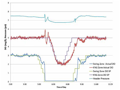
Figure 6: Dissolved oxygen (DO) set points and actual DO in swing zones and IFAS zones
EXAMINING THE RESULTS
In the first phase of the system start-up the BACS aeration control portion of the control system was tuned while the BIOS process control remained switched off.
Good control of the blowers is critical to controlling aeration, and this was achieved in close cooperation with the blower manufacturer. Blowers are typically controlled to maintain a constant pressure rather than a specified flow rate, so the master controls of the single-stage centrifugal blowers used at the Lebanon plant had to be reprogrammed for this application. In the end, the blowers could reliably and repeatably achieve flow rates within 1 percent or 25 scfm of the set point. The transition phase when blowers are switched on or off to meet changing demands was also well managed by the blower master controls.
The aeration control was tuned to limit set point changes to a pace that the blowers can match, to ensure fastest possible system response to loading changes without instability.
The aeration control logic also opens and closes air flow valves (in this case butterfly valves with modulating duty actuators, as is common in WWTPs) to distribute the air to the control zones according to the calculated needs of the respective zones. It uses a dynamic most-open-valve (MOV) logic so that the blowers always operate at the lowest possible system pressure, which minimizes aeration energy. In the case of Lebanon, this means whenever the swing zones are aerated, the MOV is on one of the swing zones, because these zones, with fine bubble diffusion, will have a higher restriction than the IFAS zones with their coarse bubble diffusers. When the swing zones are not aerated, their valves will close and the MOV will move to one of the IFAS zones. At the same time, the system pressure will drop from about 7.55 psi with aerated swing zones to about 6.75 psi when only the IFAS zones are aerated. This requires that the transition conditions be well managed to prevent pressure oscillations and resulting instability. The interaction between the blower master control and the aeration control was tuned to achieve this without disturbances.
DISSOLVED OXYGEN COMPARISONS
Figure 6 shows the dissolved oxygen (DO) set points and actual DO in the swing zones and IFAS zones through a complete on-off-on cycle of aerating the swing zones, with a corresponding reduction and increase in the DO set points of the IFS zones. You can see that the DO set points slowly ramp down to ensure stable operation, and the actual DO tracks well with only minimal lag. The header pressure also stabilizes quickly at the respective system pressure.
Using the fan law for constant diameter impeller fans:
Q1/Q2 = (RPM1/RPM2);
P1/P2 = (RPM1/RPM2)2;
PWR1/PWR2 = (RPM1/RPM2)3
at equal flow Q1 = Q2, you find that at P1 = 7.55 psi and P2 = 6.75 psi
PWR2/PWR1 = (6.75/7.55)3/2= 0.845
Therefore, at the lower pressure the blowers are drawing 15.5 percent less power. This adds up to a significant cost and energy savings over the life of the plant.
THE FUNCTION OF THE BIOS
The BIOS process control part of the integrated controls concept was started up after the aeration controls were tuned and proved to be stable.
The function of the BIOS is to:
- determine the precise amount of aeration required to achieve the process goals, which includes calculating the optimal DO set points in all aeration zones and aerating the swing zones whenever the aerobic capacity is needed
- control the internal recycle rate to maximize denitrification in the first anoxic zone without overloading the system
- control the trickling filter bypass to add carbon to the first anoxic zone whenever it is carbon deficient.

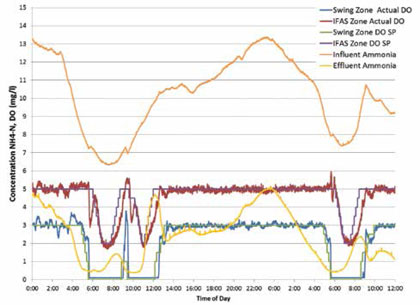
Figure 7: Performance of the integrated BIOS and BACS
Figure 7 shows the performance of the integrated BIOS and BACS over a 36 hour period. It shows how the BIOS reacts to the changing load, as represented by the influent ammonium concentration, by adjusting the DO set points of the IFAS zones and switching the swing zones between a DO of 0.0 (off) under low loading conditions and 3.0 (on) when the ammonia levels are higher. Since the BIOS calculates the reaction rates (ammonia removal rates) as a function of temperature, biomass, hydraulic retention time, residual DO levels and other factors, the switch point for the swing zones is variable. It is not sufficient to simply select an ammonium level at which to switch the swing zones between aerated and anoxic.
Over the described period the swing zones are aerated for 75 percent of the time, so the aeration savings based on the most-open-valve logic alone add up to about 4 percent. The DO set point control adds about another 15 percent savings, for a total of 19 percent aeration energy savings. Since the aeration blowers are by far the largest energy consumers in any wastewater treatment plant, typically making up 50 to 70 percent of total energy usage, this is a significant contribution to both the sustainability and the cost structure of the plant.
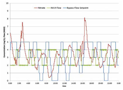
The BIOS also controls the mixed liquor recycle flow (IMLR) and the trickling filter bypass flow to improve denitrification performance and total nitrogen removal. Figure 8 shows the response of the BIOS to changing nitrate levels in the effluent flow.
The goal is to load the anoxic zone with the highest possible level of nitrates that can be processed under the given conditions, and introduce the precise amount of carbon via the trickling filter bypass that is needed to process the nitrates. It can be seen in the graph that as the nitrates drop below a set point of 2.5 mg/l the IMLR increases to increase the nitrate loading, and the bypass increases to add additional carbon. As soon as the effluent nitrate exceeds the target the IMLR decreases. At the same time the bypass flow drops when the nitrate readings drop below the set point and increase when the nitrates start to climb, but the bypass flow continues to add carbon to treat the increased nitrate levels even after the IMLR drops. The bypass flow decreases whenever the nitrate levels drop below the set point.
With these control systems, the plant is consistently meeting its process goals.

Figure 8
SUMMARY
The City of Lebanon Authority Wastewater Treatment Plant was tasked with achieving stricter nutrient removal limits without physically expanding the plant. An additional objective was to improve the sustainability of the plant by minimizing energy consumption. To support this goal it introduced a holistic process control system to optimize the operation of the secondary treatment, which consists of an IFAS system with anoxic swing zones.
The control system integrates the control of the blowers, the airflow valves, the mixed liquor recycle rate and a trickling filter bypass. The controller demonstrated that it can consistently and reliably meet the process goals and provides aeration energy savings of about 19 percent over static control systems. ■
About the Author
Tilo Stahl, PhD is a systems engineer at BioChem Technology, Inc., and Frank DiScuillo Jr. is the superintendent of the Lebanon (Pennsylvania) Authority Wastewater Treatment Facility. BioChem Technology specializes in the monitoring, optimization, and control of wastewater treatment processes. For more information, visit www.biochemtech.com. The consulting engineer and process designer on the project was K. Friedrich Updegraff, vice president at Gannett Fleming, Camp Hill, Pennsylvania.
MODERN PUMPING TODAY, September 2014
Did you enjoy this article?
Subscribe to the FREE Digital Edition of Modern Pumping Today Magazine!


