One of the pumps I am handling in my current project is an OH2 self-venting centrifugal pump. It is designed for a capacity of 194.23 cubic feet (5.5 cubic meters) per hour, a head of 138.78 feet (42.3 meters) and its motor rating is 5.5 kilowatts. The pump shall be used to transfer diesel fuel (having Specific Gravity of 0.83) from a main diesel storage tank to a generator’s diesel day tank. By having a pump of a self-venting design, the pump’s casing will not have a venting connection. This is because the pump’s discharge flange is directly on top of the suction flange (90 degrees to suction flange center line). As a result, all vapors entrapped in the pump’s casing or coming with the pumped fluid will be vented directly through the discharge flange. In addition, the self-venting design will remove the requirement of having a separate venting piping at site. This means savings in construction work, time, and operational duties.

THE SEAL ISSUE
The diesel pump was designed to have a single mechanical seal with API seal flush plan-11. API seal plan-11 is one of the flushing plans that are implemented for single mechanical seals. The flushing fluid recirculates from the pump discharge to the seal through a control flow orifice. The flushing fluid removes the heat generated in the seal chamber due to the rotation of the mechanical seal faces. Moreover, the fluid’s recirculation increases the seal chamber’s pressure above the pumped fluid vapor pressure.
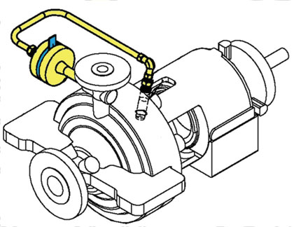
After receiving the pump’s General Arrangement Drawing, it was noticed that the seal plan-11 piping was ascending and then descending with a vent valve (see figure 1). The vent valve is necessary to vent all the entrapped air and vapors in the seal chamber before starting the pump. The reason for introducing this arrangement, as explained by the pump vendor, is the pump’s small size. Therefore, a continuously rising seal flushing piping from the seal chamber to the pump discharge cannot be achieved due to space and manufacturing constraints.
CONSEQUENCES OF THE PROPOSED DESIGN
By having a vent valve in the API seal plan-11 piping, the pump’s operator will need to open it every time the pump is started, so all the entrapped air / vapors in the seal chamber can be released to atmosphere in order to have a uniform and adequate fluid recirculation flow. As a result, the aim of having a self-venting pump will not be achieved.
In addition, the possibility that the pump’s operator does not open the vent valve, which will eventually lead to damaging the seal faces. This will increase the seal faces’ temperature due to the fact that the required flushing flow is not achieved because of the entrapped vapors. On the other hand, if the operator started the pump and forgot to close the API-11 vent valve, diesel will be flowing out to the atmosphere leading to product loss, pollution, and definitely mechanical seal failure. The mechanical seal will not have sufficient lubrication, and the seal faces’ temperature will increase due to friction and they will be damaged eventually.
PROPOSED SOLUTIONS
The mechanical seals standard API-682 3rd ed. paragraph 6.1.2.20a states the following:
On small horizontal pumps where the elevation of the discharge nozzle is not high enough to achieve a continuously rising Plan 11 flush line, then the connection may be located in the process piping upstream of the check valve if approved by the purchaser.
This seems to be a solution to our issue, but it was determined to be unworkable in this particular case by our process department and hence, another solution to be investigated.
After searching in my company’s internal database for a pump having similar size, operating conditions, and seal system, a similar pump from a previous project having API seal plan-11 was found. The pump’s seal plan piping was connected from the discharge flange to the side of the seal (not to the top of the seal chamber). For a glance, this arrangement was a hope for solving the issue, but it was not according to API-682 3rd ed. and it will have a cost impact if applied at this stage of the project as indicated by the pump’s vendor. So another solution needed to be found.
SOLUTION
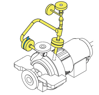
In order to have a completely self-venting pump with a continuously rising API plan-11 flush line and complying with API-682 3rd ed., our rotating engineers’ team have decided to modify the plan-11 flush line from being piping to tubing (see figure 2). This solution was communicated to the pump’s vendor and was accepted without claiming any cost impact. And hence, the design was changed and the issue was solved.
By having tubing instead of piping, the API seal plan-11 can be continuously rising within the small amount of space available between the discharge flange and the seal chamber. And hence, no vent valve will be required and all of the entrapped vapors will be vented directly to the discharge flange. Furthermore, this solution eliminated the chances of operator’s mistakes while operating the vent valve. Finally, the pump will be fully self-venting, having adequate flushing flow, and is complying to API-682 3rd ed.
ABOUT THE AUTHOR
Khaled Ayoub is a rotating engineer for Petrofac Engineering and Construction, one of the world’s leading oilfield service companies. He can be reached at khaled.ayoub@petrofac.com. For more information, visit www.petrofac.com.
_________________________________________________________________________
MODERN PUMPING TODAY, October 2013
Did you enjoy this article?
Subscribe to the FREE Digital Edition of Modern Pumping Today Magazine!


