mechanical seal")
Figure 3: Close-up of a 5-inch Model CDPH (Cartridge-Style Dual) mechanical seal.
An overview of mechanical seal experience in the mining industry is conveniently obtained by examining sealing options and technologies found in the potash industry. Although this two-part article gives such an overview by delving into the business aspects of the potash industry, our approach serves as a reasonable template for other minerals retrieved by mining. After first giving a few highlights of what potash is all about, we will concentrate on the water saving aspects of sealing systems engineered to save both water and maintenance money.
USING POTASH TODAY
The term “potash” dates back to antiquity and is derived from wood ash kept in metal pots. Pots were a commonly used storage method for this potassium-rich fertilizer. The term potash has carried over to a number of different mined and manufactured salts that contain “K” (for Kalium—a name derived from the Arabic “Alkali”) in water-soluble forms.
Over 14,000 different uses have been claimed for salt. As regards potash, we single out agriculture and all plant growth processes. In these processes, potash is a highly important nutrient. Today’s industrial scale fertilizer production depends on efficient large-scale potash mining operations. However, cost-saving efficiencies remain important in virtually every process operation that follows the initial rock mining or salt manufacturing steps.
DILUTION BY WATER NOT ADVANTAGEOUS
Once mined, the rock has to be crushed and impurities must be removed. Saturated brine, which will not dissolve potash solids, is used to process the ore through a series of scrubbers to remove insoluble minerals. The introduction of plain water into a post-crushing stage would dissolve potash solids and thereby reduce the potash yield. Therefore, cost-conscious plant operators want to prevent flush fluids from entering the process through “standard” mechanical seals in their centrifugal pumps.
WATER ENTRY LOCATION AND USAGE RATE ARE KNOWN
Each gallon of water added to the process dissolves approximately 1 pound of potash. In general, the point of entry for water is the packing box (or seal housing) on the process pump. The packing box is located behind the pump impeller—the location where the rotating shaft meets the environment. With inadequate sealing strategies, seal water will either leak to the environment or into the process. Neither leakage path is desirable.
Pump feed capacities through the scrubbers and the floatation circuit are typically rated between 1,000 to 2,000 gallons per minute (GPM). For this capacity the slurry pump manufacturer specifies a water flush of 14 to 16 GPM and, conservatively, one third of this flush directly enters into the process. Using a potash market price estimation of $500/ton; the flush water entering the process through the pump results in potash losses of $613,200 per year.
Fortunately, this process flush water practice does not have to remain a cost burden; water entry can be eliminated using an alternative seal arrangement. The conversion cost estimate for this alternative is less than $20,000, which provides a highly attractive return-on-investment of just twelve days. In order to optimize performance, it is essential to combine the correct mechanical seal design with a stuffing box design that prevents clogging and erosion. The issue is addressed and the problem solved by connecting the seal to a suitable off-the-shelf water management system.
Our two-part article provides guidance on the selection variables relating to available water management systems. Particular emphasis is given to application experience that best highlights the business case.
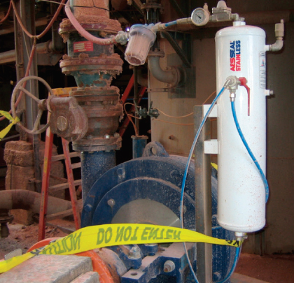
Figure 1: Seal support system on a Tailings Pump. This mining pump was put in service in early 2010.
CASE HISTORY: A MINE LOCATION IN NEW MEXICO
A major seal manufacturer has worked with a well-known mining pump manufacturer for many years. At that time the seal and system solution which is detailed here was installed at a corporation based in New Mexico, USA. The paragraphs that follow make reference to this and other successful applications.
In a brine flotation tower service three mining pumps continue to run after accruing an estimated 22,500 operating hours. Used in conjunction with a suitably selected mechanical seal, the seal support system shown in figure 1 resulted in flush elimination of 6 GPM, or 360 GPH. For the three pumps involved in this service, 360 GPH equated to water savings of 8.1 million gallons per year. A second pump is shown in figure 2; it uses a 5-inch Cartridge-Style Dual) mechanical seal (“CDPH”, see figure 3). Potash recovery savings were 4,050 tons. At a market price of $500 per ton, this potash producer will have saved $2,025 million.
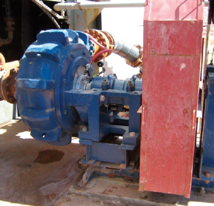
Figure 2: Side view of the size 8×6-28 Talings Pump
SEAL SELECTION, SEALING OPTIONS, AND FLUID FILM CONSIDERATIONS.
Sealing options are largely influenced by long-standing industry conventions. Slurry pump manufacturers recommend expellers (or “repellers”), mechanical packing, or single mechanical seals on slurry pumps. Whenever any of these three arrangements are used to seal the process pumps in the mine’s scrubber and floatation circuits, the manufacturer requires a clean-water external water flush to be injected into the pump stuffing box. The American Petroleum Institute (API) Piping Plan 32 is the industry standard.
Figure 4 depicts a water line from an external water source connected to the back of the pump process at the packing/seal chamber. This is where the rotating shaft exits the process casing and is a sealing point. Pump manufacturers specify the seal water to be injected at 10 psi above the discharge pressure of the pump. The water enters the volute casing in the stuffing box, directly behind the impeller. About one third (or more) of the flush water enters into the process stream because it is entering at a higher pressure. The remaining two-thirds of the flush water leaks to the floor area surrounding the pump. If there is little outward leakage, a greater portion of the flush water enters the process fluid. This inward leakage dissolves the potash and reduces potash production yield, as outlined above.
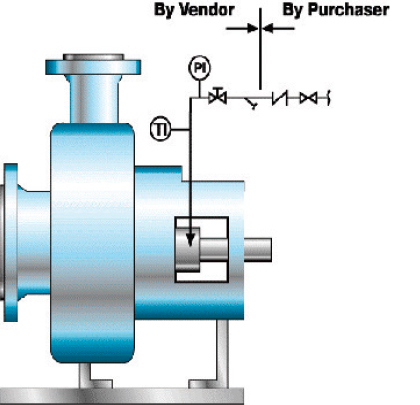
Figure 4: API Flush Plan 32 shows water injection from an external source.
Expellers (dynamic seals) force fluid back into the pump volute during operation. A set of packing rings or lips seals behind the expeller seal the shaft in intermittent service. The expeller is limited by the pump inlet pressure. One manufacture recommends the maximum inlet pressure on a 1,500 GPM application should not exceed 9 psi to achieve leak-free performance. This means the expeller option is not suitable for high pressure tailings pumps, for example, and leads to the mechanical seal selection option.
Single Mechanical Seals, figure 5, are specially designed for slurry operation. In order to understand the rationale behind double mechanical seals, consider the sealing points in a standard cartridge mechanical seal. Figure 5 shows where an O-ring seal the shaft, a dynamic elastomer accommodates axial motion of the rotary assembly, a gasket seals the housing and the rotary face (in yellow) seals against the stationary face (in dark blue). A fluid film between the two seal faces (or surfaces) creates the seal between the rotation of the shaft and the stationary housing of the rotating equipment. If this fluid film is not controlled consistently, the faces will leak. As slurry builds-up on the atmosphere side under the seal stationary face, additional wear and damage is likely to occur.
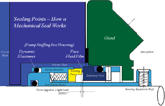
Figure 5: An O-ring seals the shaft, a dynamic elastomer accommodates axial motion of the rotary assembly, a gasket seals the housing, and the rotary face (in yellow) seals against the stationary face (in dark blue).
Special slurry single seals, figure 6, are designed with the idea of “grinding” the slurry between the seal faces. As they leak, wider clearance may be used to wash away leakage. Single slurry sealing is fine in theory. However, we want to think through what happens if the pump runs dry, or the pump suction filter clogs, or the suction lift is not immediately flooding the pump upon start-up. Under these real-life scenarios, seal performance is limited. It doesn’t matter then if one uses mechanical packing, an expeller/repeller or a single slurry seal—the fluid machine will fail.
So, there must be a better way to seal slurry pumps at reliability-focused user sites. This is why the application solutions to which we refer in this article all use dual mechanical seals. As a cautionary note, there are other variables that must be addressed beyond just installing a dual seal into the pump.
TECHNICAL ISSUES RELATING TO FLUID FILM CONTROL
A highly experienced seal manufacturer recommends the use of dual cartridge mechanical seals and a support system to control the fluid film at the seal faces. Fluid film stability can be achieved and controlled when the barrier fluid pressure is greater than the seal chamber pressure. The fluid film is controlled by the differential pressure between the barrier fluid and the process fluid.
In figure 6, process slurry is at a higher pressure than the barrier fluid. In this instance, the slurry (shown in brown) is forced into the face gap where only a clean fluid will do. Forcing slurry into the gap is not ideal; eventually the slurry will grind itself into the seal faces and the faces will no longer retain sufficient face flatness to maintain a seal.
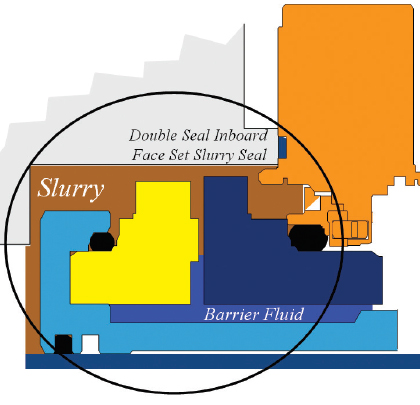
Figure 6: The slurry makes contact with the inboard portion of a double (“dual”) mechanical seal. The outboard portion (not shown) is making contact with a clean barrier fluid (blue). Due to an incorrect diffrential pressure, slurry has entered the face gap in this seal.
With the correct pressure controls in a double mechanical seal, the clean barrier fluid is at a higher pressure and it is forced across the seal faces. From closely observing the film between the rotary face (in yellow) and the stationary face (dark blue), one notes the clean blue color barrier fluid (figure 7).
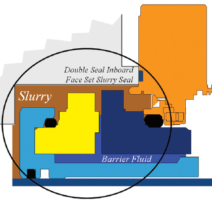
Figure 7: The slurry makes contact with the inboard portion of a double (“dual”) mechanical seal. However, with the correct differential pressure between a clean barrier fluid (blue), only the clean fluid is found in the seal gap.
A LOOK AHEAD
If the seal face fluid film can be stabilized to ensure long-term reliability, the next technical point to address is how to minimize the wear on the seal components exposed to the slurry. This is done by selecting a seal chamber configuration that minimizes erosion of the seal parts. It also involves a decision process between using standard ANSI type mechanical seals in light slurries and heavy duty thick cross section parts in heavy slurries. Part 2 of this article addresses the issue.
About The Author
Tom Grove is the president and CEO of AESSEAL’s U.S. branch. AESSEAL Inc. is one of the world’s leading specialists in the design and manufacture of mechanical seals and support systems. He can be reached at tom.grove@aesseal.com. Heinz P. Bloch, P.E., is one of the world’s most recognized experts in machine reliability and is a Life Fellow of the ASME, in addition to having maintained his registration as a Professional Engineer in New Jersey for several straight decades. As a consultant, Mr. Bloch is world-renowned and value-adding. He can be contacted at heinzpbloch@gmail.com.
_______________________________________________________
MODERN PUMPING TODAY, May 2018
Did you enjoy this article?
Subscribe to the FREE Digital Edition of Modern Pumping Today Magazine!