By Eugene Vogel, EASA
Submersible pumps may have any of several types of internal sensors or protective devices, including temperature sensors, vibration transducers and moisture sensors. Of these, only moisture sensors are unique to submersible pumps and deserving of special attention. To ensure that these devices work properly in the submersible pumps they repair, technicians need to recognize their presence and understand how they work.
MOISTURE SENSOR INDICATORS
When moisture sensors are present in a machine, commonly the power cable will have extra control leads connecting the sensor to the starter or controller. In some instances, the control leads may be in a separate cable. Generally, though, the presence of control leads entering the pump with the power leads indicates moisture sensors may be present (see figure 1).
An important initial step in disassembling a submersible pump is to remove the cable seal housing (aka pot housing) and inspect the incoming leads. Since the cable or cord usually enters at the top of the submersible pump stator and any moisture sensors will naturally be below the stator, it is necessary to disconnect any moisture sensor leads before removing the stator from the pump. Attempting to remove the stator without disconnecting the moisture sensor leads will break those leads or possibly damage the moisture sensor.
SEPARATE SEALED CAVITIES
Submersible pumps have two separate sealed cavities–the motor stator cavity and the seal cavity. Industrial models have two seals with a seal cavity between them filled with a barrier fluid, usually oil or a glycol solution. Each of these two cavities is subject to possible moisture ingress and may have moisture sensors. In one common configuration, a pair of dual-purpose moisture sensors may protect both the stator and seal cavities. In other configurations, individual sensors may protect either or both cavities. The arrangement and purpose of the sensors should be obvious from their locations, but not from the control leads at the cable or cord connection where testing may be done.
COMMON TYPES OF MOISTURE SENSORS
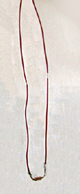
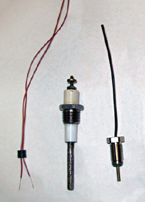
The most common types of moisture sensors are conductivity probes (see figures 2 and 3). These usually consist of an exposed metal conductor mounted in an insulator, but some are simply a length of tinned lead wire. Conductivity probes (figure 2) may employ a single sensor with an electrical potential to ground or a pair of sensors with the electrical potential between them. In either case, the presence of moisture will reduce the resistance in the circuit, prompting the pump controller to indicate a moisture failure.
Note that there is a resistor between the probe terminals in figure 3. The pump controller is set to recognize that resistance value, allowing it to detect if a sensor lead is open. To determine a resistor’s nominal value from its color band markings, consult an electrical reference such as EASA’s Electrical Engineering Pocket Handbook.
Figure 4 illustrates a pair of dual-purpose moisture sensors that have the sensor circuit between the two conductivity probes rather than from one sensor to ground. The probes mount through holes in the bottom of a well in the stator cavity and extend into the oil-filled seal chamber beneath it. When moisture collects in the stator cavity well, it closes the circuit between the terminals on the top of each probe. If the outer (lower) seal fails and pumpage enters the oil-filled seal chamber, that moisture will mix with the seal oil, reducing the resistance between the immersed portions of the probes. Thus these probes sense moisture in the seal cavity or moisture in the stator cavity.
FLOAT SWITCH SENSOR
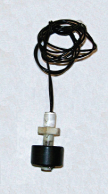
Perhaps the simplest type of moisture sensor is a float switch sensor (see figure 5). The float is magnetic and closes (or opens) an isolated reed switch when the float rises. Unlike other types of sensors, float switches are functional only when the pump is vertical—i.e., the normal operating position for submersible pumps.
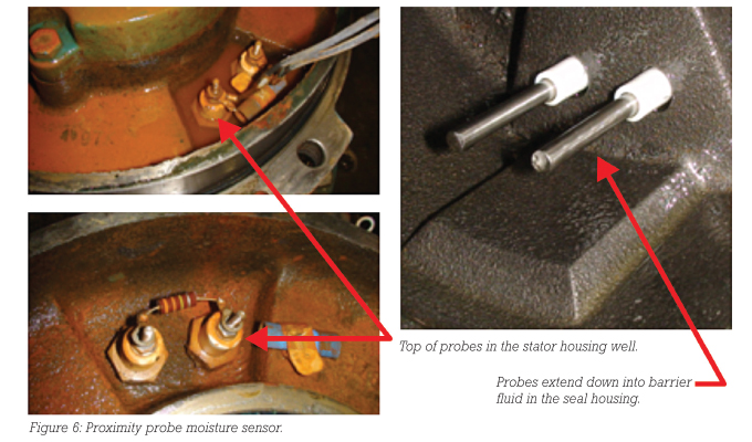
PROXIMITY PROBES
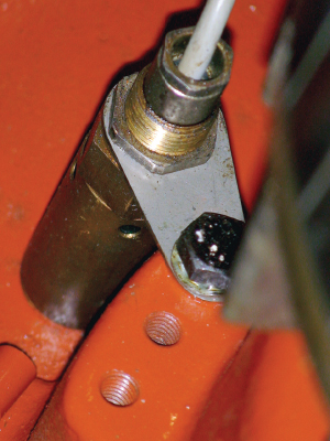
Figure 6 illustrates an unusual proximity probe moisture sensor. When moisture accumulates as water in the well at the bottom of the stator cavity, the proximity sensor detects the change in density near the tip of the detector.
TROUBLESHOOTING IN THE FIELD
Evaluating and testing individual moisture sensors during the repair process is a simple matter. Troubleshooting fault indications on an installed pump can be more difficult. In some instances, manufacturers connect various temperature and moisture sensors in series, bringing out only two leads. To test that series circuit, the resistances of individual sensors and trim resistors must be known. Programmed controllers may report a high temperature fault or a moisture sensor fault, depending on the circuit resistance change. But a faulty sensor can trick the controller; a faulty moisture sensor could trip a temperature fault or vice versa when the only fault is with the sensor.
CAUTION DURING REPAIRS
Repair technicians should recognize the presence of moisture sensors in submersible pumps and be familiar with how each type operates. During the disassembly and repair process, they also should handle moisture sensors carefully to prevent damage and test them to ensure they function properly.
FOR MORE INFORMATION
Eugene Vogel is a pump and vibration specialist at EASA, Inc., the Electrical Apparatus Service Association. EASA is an international trade association of more than 1,800 firms in nearly seventy countries that sell and service electromechanical apparatus. For more information, call 314.993.2220, fax 314.993.1269, or visit www.easa.com.
MODERN PUMPING TODAY, April 2021
Did you enjoy this article?
Subscribe to the FREE Digital Edition of Modern Pumping Today Magazine!