Control valves (CV) are found throughout municipal water distribution systems and are integral to maintaining consistent water pressure and supply. The importance and ubiquity of control valves underscore their significance in the functionality and reliability of water distribution infrastructures. To ensure the CV provides the functionality required with years of trouble-free operation, it’s important to select the correct size of valve and accessories, while providing a well-designed environment for the operational personnel that will have to maintain this valve.
SIZING YOUR VALVE

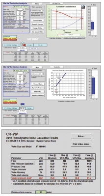
Most valve stations in municipal water situations are pressure reducing valves and selecting the right size is important, as problems can arise from incorrect sizing. Rather than sizing the valve based on line size, it is necessary to consider flow, pressure, and velocity. Knowing the size of the water main and the maximum, average, and minimum flow demands, one can move forward in the valve size selection. Some manufacturers, like Cla-Val, have a sizing software program that makes it quick and simple to size a valve correctly, but understanding what the program is considering is useful.
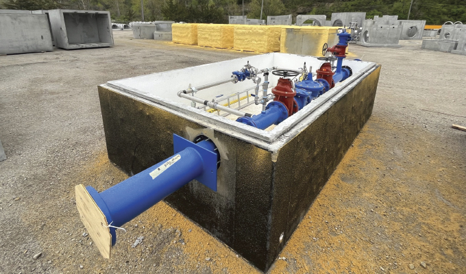
A software program will select a valve size based on the maximum required flow the valve has to pass, based on the minimum system differential pressure. This will be the upstream pressure minus the required downstream pressure that the reducing valve will be set at. The program will consider the velocity passing through the valve—it is best to limit this to 20 feet per second in valves operating continuously. In valve stations, it is common to have two control valves in parallel. The larger valve on the main line is designed to take care of peak flows, while the smaller second valve on a bypass will take care of low flows. Typically, the smaller, bypass valve will be sized to handle approximately 20 percent of the peak flow.
The smaller valve is also set slightly higher in pressure than the large valve. This allows the smaller valve to open first in the sequence, followed by the large valve as flow increases. The smaller valve is also the last to close as flow diminishes. This bypass line also offers redundancy as either of the valves can be used to supply the network while the other is being serviced. This is particularly important where it is not possible or practical to shut off the main water supply for periods of time.
Some manufacturers have software to support valve station design and allow engineers to consider the impact of velocities, among other things. Often, the velocity in a bypass valve can be excessive, potentially causing damage to the small valve and increasing loud noise levels. Using software, a designer can specify the use of a transition device that will bring the main line valve into operation before high velocities are reached, which is often before the lower pressure setting of the larger valve.
CONSIDER THE RISK OF CAVITATION
Anytime there is an application where reductions from a higher pressure to a lower pressure, and that ratio is greater than 3:1, there is a real risk of cavitation. This phenomenon will destroy a valve over time due to erosion and can create noise and vibration in the pipeline that may be a problem for nearby residents. However, unlike in days past when multiple valves would have to be installed to stagger the pressure drops, this can now be achieved through an anti-cavitation trim. This is a specific trim consisting of two stainless steel cages with slotted openings or drilled orifices, that contain the cavitation in the center of the cages, eliminating the disastrous erosion issues.
It is always recommended to run a cavitation software program to determine if cavitation will be a problem, and this should be a program specific to the manufacturer’s valve. Generic programs are available but do not account for the actual body shape of the valve.

OPTIONS TO CUSTOMIZE
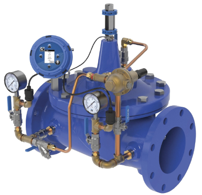
The real advantage of diaphragm-actuated globe valves is that one can have a pilot system tailored to a specific application. Numerous features can be added to give a custom solution that provides real operational benefits.
Stainless steel pilot systems are popular and the price differences to brass/bronze or copper is not restrictive, and it should last longer, particularly in harsher environments. Pilot systems can be installed on either side of the control valve so give some thought to the location for accessibility with ladders and also clearance for maintenance. Pilot tubing is frequently stepped on or knocked because of poor placement—with a little forethought, this is avoidable.
The pilot system should always be installed with a strainer and can be a flow clean, internal style, or an external Y-strainer style. In tough applications, a water filter can be used. Pilot isolating valves are vital for maintenance and troubleshooting of the valve – even on the smallest of valve sizes.
A LOOK AHEAD
In the conclusion of this piece, we’ll examine further customization options, including options to give more system control. Additionally, we’ll look over key considerations for design layout and which practical and functional additions are best considered before a valve station is installed.
Mark Gimson is director of marketing and international sales for Cla-Val. As a mechanical engineer with forty years in the water industry, Gimson has a passion for expanding markets and understanding customer challenges to provide the optimal solution. Cla-Val is a world-leading designer and manufacturer of automatic control valves. From reducing and relief valves to deluge, air valves and more, Cla-Val manufactures and provides a wide variety of solutions for use in some of the world’s most demanding applications. For more information, visit www.cla-val.com.


