Seal performance in slurry services is largely influenced by two parameters: The design of the seal chamber and maintaining proper control of the fluid film. The conventional option is an open throat seal chamber shown in figure 8.
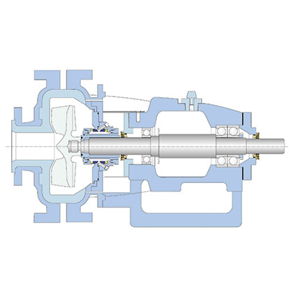
Figure 8: Open throat seal chamber in a slurry pump
SEAL SELECTION AND CHAMBER DESIGN FOR POTASH AND SIMILAR MINING SLURRIES
However, this design can have problems with erosion at the seal gland, caused by the velocity of the slurry around the seal face. The remedy is to use flow modifiers (ridges) machined or cast into the inside diameter of the seal chamber. In addition, the back-vanes on the impeller are usually filled in, if a seal is used, to prevent dry running.
The second option (not shown) is to mount a mechanical seal into a stuffing box that had originally been designed for braided packing. Suppose the design intent was to use ½” cross section packing; for standard packing boxes this means there is about 1/8” clearance around the seal rotary. As heat is generated by the seal, the process fluid de-waters and compacts around the rotating seal. As this occurs the packing box eventually becomes clogged and the seal parts wear; fluid film is lost, which shortens life and ultimately leads to failure.
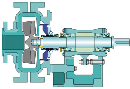
Figure 9: Slurry pump with large seal cavity
Figure 9 shows the third option, which is used in the applications described in Part 1 of this 2-part article. Note the large cavity around the seal. The slurry velocity is interrupted by the closed frame plate between the impeller and the seal chamber. The seal mounts to a seal back plate, machined so that standard off-the-shelf seals can be used.
SEAL SELECTION: HYDRAULIC INSTITUTE SLURRY DEFINITIONS
Seal selection differs with the severity of the slurry. The ANSI Hydraulic Institute Rotodynamic (Centrifugal) Slurry Pump Standard, 12.1 – 12.6-2005 specification for centrifugal pumps classifies slurries based on a Miller Number, which is actually a value tied to abrasive wear on standard reference materials. Factors such as particle hardness, size, and shape as well as corrosiveness can affect the Miller Number.

Table 1: The four Slurry Classes
Slurries are ranked in four possible classes (Table 1):
- Class 1 = Light
- Class 2 = Medium
- Class 3 = Heavy
- Class 4 = Very Heavy
The class ranking for slurries is linked to the slurry specific gravity, concentration by volume (as a percentage) and average d50 particle size (in microns). At least one major seal manufacturer uses this guide to select the best seal for the application; this manufacturer accommodates the stipulations found in the ANSI Hydraulic Institute Rotodynamic (Centrifugal) Slurry Pump Standard, 12.1 – 12.6-2005 by using Table 1:
EXPLAINING THE SEAL TYPES USED IN SLURRY SERVICES
CDSA is the designation for a prominent manufacturer’s cartridge-mounted double mechanical seal. The seal operates in either rotational direction; it is built on a modular face component platform. The seal’s rotary is loaded by individual Alloy C276 springs all of which are out of the process fluid. Inboard and outboard stationaries are interchangeable, monolithic, and available in silicon carbide or tungsten carbide. CDSA can be mounted in horizontal or vertical orientation. Glands are available for standard bore and ANSI-Plus stuffing boxes. Smaller frame pumps using 5/16-inch cross section packing can be retrofitted with a CDSA without modification to the pump.
Another seal type is designated CDPH—essentially a cartridge-mounted heavy-duty double mechanical seal. It, too, allows operation with clockwise as well as counterclockwise rotation; its wetted components have large cross-sections. In a CDPH the rotating assembly consists of a 316L stainless steel holder; inserted into this holder is a press-fitted rotary face, available in carbon, tungsten carbide or silicon carbide. The inboard rotary is again loaded by individual Alloy C276 springs and all springs are out of the process media. The inboard rotary is designed with reverse face balance in order to withstand process system upsets. Inboard and outboard stationaries are interchangeable, monolithic, and available in silicon carbide and tungsten carbide. In most designs, the area below the stationary seal faces is enlarged for maximum cooling and circulation.
CONTROLLING BARRIER FLUID PRESSURE
With the decision on the seal type and an optimised seal chamber, the discussion reverts back to how to control the barrier fluid pressure and the general quality of the barrier fluid, outlined earlier in Part 1 of this 2-part article.
The control of the fluid film is a function of the piping plans and control systems used to ensure the barrier fluid is always at a higher pressure. Moreover, the system must be sized and configured to remove the heat generated by the seal faces. Water management systems are pre-engineered to satisfy all requirements.
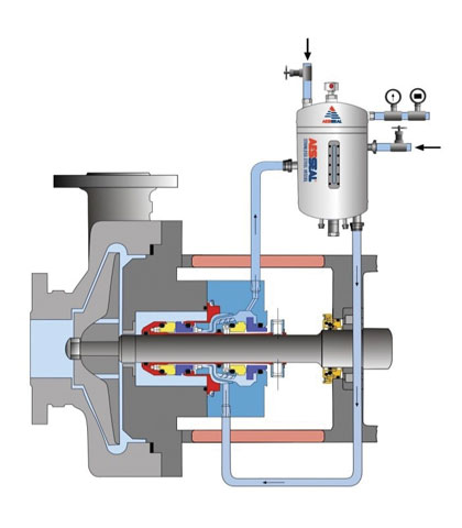
Figure 10: Plan 53A
Seal Support Systems and Piping Plans
Piping plans for double mechanical seals fall under API Plan 52, Plan 53-(A, B, C), or Plan 54. Plan 53 (figure 10) has a seal pot mounted above the pump and a fixed volume of liquid; the tank is charged with nitrogen to set a higher differential pressure between the pot and the box (Plan 52 has a lower differential pressure). If the inboard seal leaks (e.g. cavitation), the nitrogen forces the fixed volume of liquid into the pump and the seal runs dry if the tank barrier fluid is not immediately replenished.
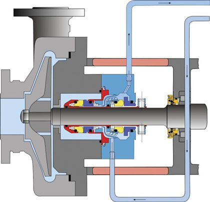
Figure 11: Plan 54
Plan 54 (figure 11) is a pressurized water-to-drain arrangement (or water is circulated by an external pump back to a holding tank), where the pressure is provided by an external seal water pump. The problem with a water-to-drain set-up is that it is difficult to control the consistent flow and pressurization of barrier fluid to a bank of pumps from a common pump header.
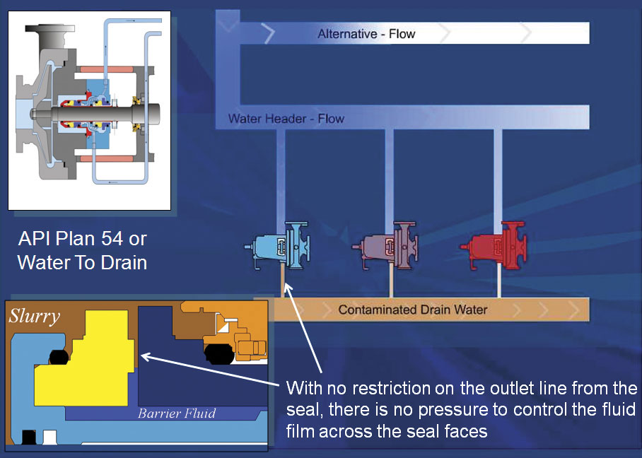
Figure 12: Slurry is highly undesirable as a fluid film in mechanical seals
The representations in figure 12 illustrate the problem. Three pumps are connected to a common header, the pump on the right is starved because an operator taps into the seal water to wash-down the area and directs water to an alternate flow / use. When the pump on the right fails, it cross contaminates the other pumps if the line returns to a central holding tank. In addition, the water flowing through the seal is like a garden hose. If there is no resistance to the outlet pipe, the water has flow and no pressure. This means the slurry ends up serving as the fluid film (in the inset) since the pressure across the slurry is higher than the differential pressure from water header to open drain. Slurry does not serve us well as a fluid film.
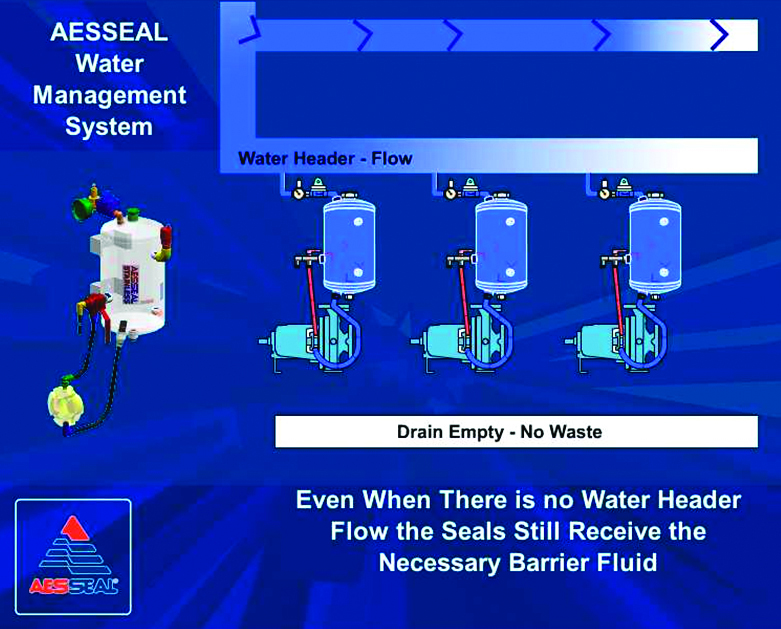
Figure 13: An advantageous water management system is depicted here
One widely used packaged solution combines two API Piping Plans: Plan 53-A and Plan 54. The advantageous water management system in figure 13 isolates the application so that the fluid film in figure 14 is controlled. Like Plan 53-A, the water management tank (figure 15) is mounted above the seal application; the system pressure is controlled by a regulator on the top of the tank. Unlike traditional Plan 53-A systems, water is connected directly to the tank from a water header, which is similar to Plan 54.

Figure 14: The slurry makes contact with the inboard portion of a double (“dual”) mechanical seal. However, with the correct differential pressure between a clean barrier fluid (blue), only the clean fluid is found in the seal gap.
If there is a loss of barrier fluid, the water source from the Plan 54 connection automatically recharges the system. A flow indicator on top of the tank indicates water is entering the system.
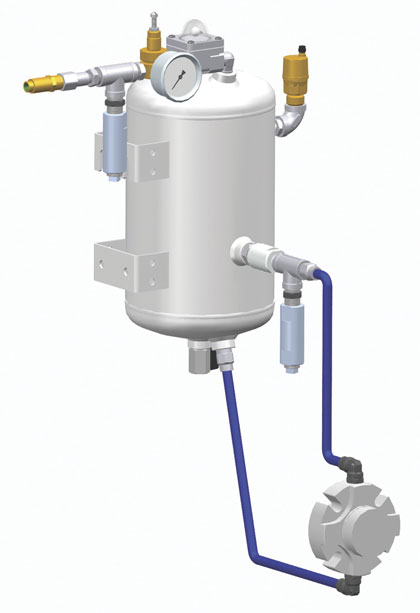
Figure 15: A modern water management tank
Water quality is controlled by using an in-line filter prior to the regulator. The filter can be replaced on-line, although filter replacement is infrequent because the filter is not exposed to continuous flow of water. With a higher differential pressure in the tank, the inboard seal face seals clean water, and does so even during process upsets.
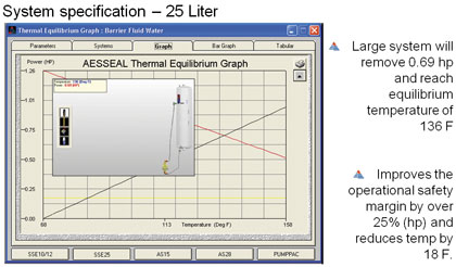
Figure 16: A thermal equilibrium graph and water system core specification
TANK SIZE CONSIDERATIONS
An experienced water systems manufacturer recommends a 6.5-gallon tank for many of the more common slurry pumps in a potash processing facility. Although somewhat smaller tanks are available, a typical heat generation graph (figure 16) shows the benefits obtained with a larger tank. Heat is dissipated over a greater surface area. This means the seal faces are sealing cooler water and heat is more efficiently dumped if the flow to the water header is interrupted or there is a process upset where the seal is operating dry on the process side.
FREEZE PROTECTION
In 2009, an abnormally cold winter at one of the various potash processing plants caused the Water Management Systems to freeze. Despite this freeze incident, the Mechanical Seals continued to perform. Since this occurrence, the plant decided to retrofit the patented Freeze-Fuse ™ option (figure 17) on its many water management systems.
During normal production runs, even when the weather is below freezing, the mechanical seal produces heat at faces. As the density of the barrier fluid changes in the seal, it rises back to the tank and circulates back to the seal from the bottom of the tank. This produces enough heat to prevent freezing.
If the plant is idle and the pumps are shut-down, the water is subject to freezing. To prevent this, the Freeze Fuse™ is fitted with a temperature sensor and by-pass valve on the return line from the seal. This device will open at approximately 34 degrees Fahrenheit (1.5 degrees Celsius), dumping water to drain from the tank and then closing again to allow circulation at 39 degrees Fahrenheit (3.9 degrees Celsius).
Look for mechanical seals and suitable auxiliaries from experienced vendors. Strive to assign extra credit to providers that can point to successful partnerships with leading slurry pump manufacturers. And as you perhaps consider different slurry pump suppliers, be certain to coordinate and/or compare procurement standards, regardless of who supplies your pumps.
About The Author
Tom Grove is the president and CEO of AESSEAL’s U.S. branch. AESSEAL Inc. is one of the world’s leading specialists in the design and manufacture of mechanical seals and support systems. He can be reached at tom.grove@aesseal.com. Heinz P. Bloch, P.E., is one of the world’s most recognized experts in machine reliability and is a Life Fellow of the ASME, in addition to having maintained his registration as a Professional Engineer in New Jersey for several straight decades. As a consultant, Mr. Bloch is world-renowned and value-adding. He can be contacted at heinzpbloch@gmail.com.
_______________________________________________________
MODERN PUMPING TODAY, June 2018
Did you enjoy this article?
Subscribe to the FREE Digital Edition of Modern Pumping Today Magazine!