By Lin Liu, Zhuang Li, and Suri Ganeriwala, SpectraQuest, Inc.
A shaft crack is a slowly growing fracture of the rotor. If undetected in an operating machine, as a crack grows, the reduced cross section of the rotor will not able to withstand the dynamic loads applied to it. When this happens, the rotor will fail in a fast brittle fracture mode. The sudden failure releases a large amount of energy that is stored in the rotating system, and the rotor will fly apart. This kind of failure may cause serious injury or even death to anyone unfortunately standing near the machine at that moment. Obviously, shaft crack detection is a very serious matter, and machines that are suspected of having a crack must be treated with the utmost caution.
Cracks are initiated in the shaft in regions of high local stress. Shafts are subjected to largescale stresses due to bending, torsion, static radial loads, constrained thermal bows, thermal shock, and residual stresses from heat treatment, welding, and machine operations. All of these stresses combine to produce a local stress field that changes periodically. In a small, local region where stresses exceed the maximum that the material can withstand, a crack will form in the material.
If the cyclic stresses are sufficiently high, the leading edge of the crack will slowly propagate so that the plane of the crack is perpendicular to the orientation of the tensile stress field. The orientation of this stress field is determined by the type of stress (bending or torsional) and by geometric factors. If the rotor is subjected only to simple bending stresses, then the stress field will be oriented along the long axis of the rotor, and the crack will propagate directly into and across the rotor section, forming a transverse crack. The pure torsional stress will produce a tensile stress field that is oriented at 45 degrees relative to the shaft axis. A crack in this stress field will propagate into the rotor and tend to form a spiral on the shaft surface. Figure 1 shows these two types of cracks. In most rotor systems, the stress field contains a mixture of bending and torsional stress. Bending stress, however, is usually the dominant component, thus the crack will usually propagated into the rotor more or less as a transverse crack.
Shaft bending stiffness is related to the shaft cross-section area. As a crack propagates across the shaft, the remaining cross section becomes smaller, and the bending stiffness of the shaft decreases. This will reduce the resonance frequency as well as the critical speed of the rotor system. The reduction in shaft stiffness also causes the rotor to bow more in response to a static or dynamic load, such as a rotating unbalance. The bow is likely to change over time. As a result, it will change the effective location and magnitude of the heavy spot, which will consequently change the 1X rotor response.
If a rotor with a crack has a steady, unidirectional radial load, then a strong 2X response may appear when the rotor is turning at half of any resonance speed. As a breathing crack involves both the closing and opening in one revolution, the rotor will respond at the 2X frequency. If a resonance exists at twice running speed, then the 2X vibration will be amplified.
In this study, a series of tests were carried out on a SpectraQuest MFS with cracked shafts to observe their behavioral changes, including the critical speed, 1X and 2X frequency responses, compared with an intact shaft.
EXPERIMENTAL SETUP
Three experiments were designed to approach the objective of this study. They were:
- Cracked shaft simulated using Flange
- Notched shaft with V-shape crack 1.6 inches from the inboard bearing housing
- Notched shaft with V-shape crack 1 inch from the inboard bearing housing
The changes of critical speeds for the intact and cracked shafts were studied in Experiments A and B. The changes of 1X and 2X frequency responses for the intact and cracked shafts were investigated in Experiments B and C. The running speeds were chosen to be 2,000 rpm and 4,000 rpm.
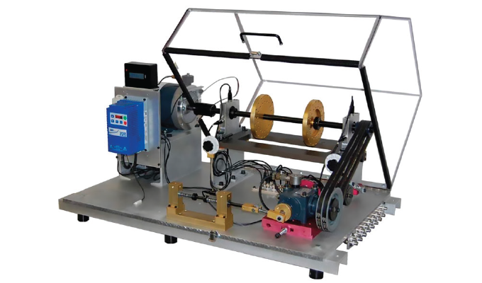
The tests were conducted on the rotor MFS which is illustrated in figure 2. Four accelerometers were mounted on the inboard and outboard bearing housings in the vertical and horizontal direction, respectively. The setup of Experiment A is shown in figure 3.
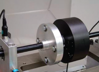
Figure 3 shows the flange-simulated cracked shaft. It consists of two separable shafts joined at the mating flanges. The four bolts compress Belleville washers that can be loosened or tightened in a pattern to create an unsymmetric time varying stiffness and simulate the opening and closing of a transverse crack. The large disc next to the flanges provides gravity loading and a shaft bending moment. Tests were run with one, two, and three bolts loosened.
The setup for Experiments B and C use a shaft with a simple 90 degree, 0.15 inch deep notch. A small tapped hole in the center allowed a small filler piece to be clamped in the notch to vary the stiffness change due to the notch. Tests were run with the filler piece removed, partially, and fully tightened.
EXPERIMENTAL RESULTS AND ANALYSIS
All experimental data have been collected and analyzed by using SpectraQuest’s VibraQuest software package. Transient, Waterfall, and Analysis tools of this software package were mainly used in this study.
Change of Critical Speeds
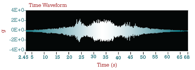
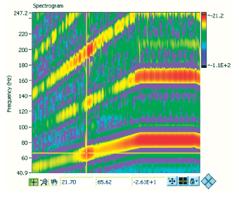
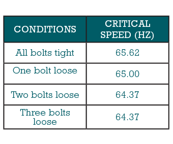
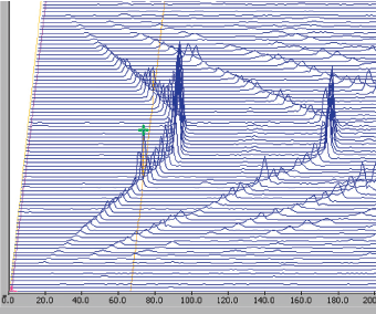
The critical speed in start-up tests can be identified by using time-frequency spectrogram, time waveform, and waterfall plot of the acceleration signals, shown as figures 4 through 6 respectively. In figure 5, the abscissa is time (second). The red spot where a cursor points represents the first critical. The cursor values indicate that the critical occurs at 21.7 seconds and 65.62 Hz. For Experiment A, the critical speeds for different cracked conditions on the shaft are listed in Table 1, where the “all bolts tight condition” condition simulates no crack on the shaft, and three-loose means the most seriously cracked condition.
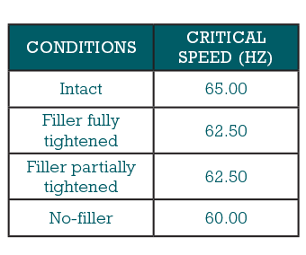
The critical speeds for different cracked conditions on the shaft in Experiment B are listed in Table 2. Intact means no crack on the shaft and “No-filler” represents the most serious crack condition. Filler fully tightened and Filler partially tightened (more serious than Filler fully tightened) stand for the middle cracked conditions.
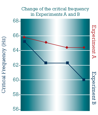
Both tables have demonstrated that as the crack grows, the critical speed decreases due to the reduced stiffness. The overall trend of these results matches the theory of shaft crack quite well. Figure 7 clearly shows this trend for the changes of critical speeds in different crack conditions.
1X and 2X Frequency Response
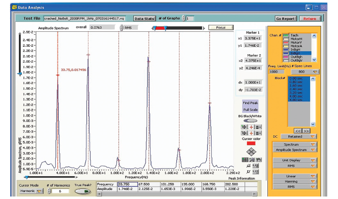
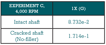
Using the analysis functions in the VibraQuest software package, as shown in figure. 8, it is easy to obtain the 1X and 2X frequency response for each steady-state test in Experiments B and C. Because the critical speeds of the rotor systems were around 60 Hz to 65 Hz, when the running speed is 2,000 rpm (33.33 Hz) in the tests, 2X will be close to the resonance frequency. So both the 1X and 2X components need to be analyzed. When the running speed is 4,000 rpm (66.67 Hz), 1X is close to the resonance frequency and 2X will be far away from it. Therefore, only the 1X frequency response has been analyzed.
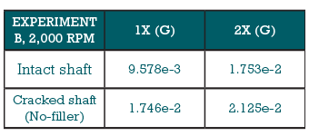
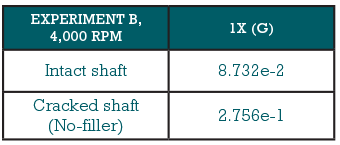
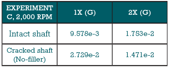
Tables 3 through 6 show the results of 1X and 2X frequency response for all cases of Experiments B and C. Comparing these results shows that normally the 1X and 2X frequency responses of the cracked shaft are larger than that of the intact shaft. This means the crack in the shaft has changed and amplified the 1X and 2X vibration responses. This result is consistent with the theoretical consequence about the shaft crack which has been mentioned before in the introduction.
SUMMARY
A shaft crack is a slowly growing fatigue fracture of the rotor. Damage of a crack failure can cause serious injury and therefore detection of shaft crack is very important. Shaft crack reduced the bending stiffness of the shaft due to the reduced available cross-section area. That will change the critical speed of the rotor system, and its 1X and 2X frequency response when the system is operated at one-half of a resonance frequency. All these provide the diagnosis for shaft cracks.
In this study, shaft cracks were simulated and analyzed using SpectraQuest rotor Machinery Fault Simulator and the VibraQuest software package. A series of experiments were conducted to observe the behavioral changes of the cracked shaft in critical speed, 1X and 2X frequency responses. The results show that the critical speed decreased as the crack increased, and the 1X and 2X frequency response for cracked shaft increased compared with the intact shaft. Those results are consistent with the theoretical consequence of the shaft crack.
FOR MORE INFORMATION
SpectraQuest, Inc. is a leading developer and manufacturer of complete turn-key Systems for training and diagnosis in machine vibration analysis, rotor balancing, and shaft/coupling alignment. System includes machinery fault simulators, interactive training program, data acquisition hardware/software, and accessories. To accelerate the learning and design process SpectraQuest offers a series of interactive software CDs on vibration fundamentals and calculations, signal processing, alignment, and balancing. For more information, visit www.spectraquest.com.
MODERN PUMPING TODAY, October 2020
Did you enjoy this article?
Subscribe to the FREE Digital Edition of Modern Pumping Today Magazine!