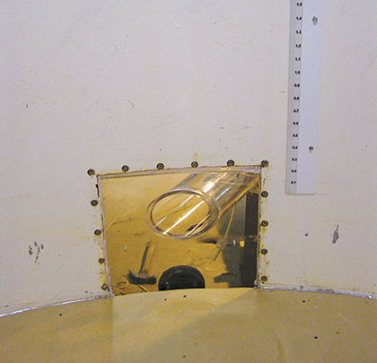
Amodel of the tank and outlet piping of interest are constructed to the geometric scale based on the considerations described above. The suction pipe geometry including the corresponding floor and wall clearance and any bends or fittings which may influence the flow patterns at the outlet suction are also modeled. The model suction piping close to the tank should be fabricated using clear acrylic pipe to provide for visual observations of any air entrainment. Other tank internal details (representing significant obstructions to the flow) which may influence the flow patterns in the vicinity of the suction should also be included.
The model setup includes piping to withdraw the appropriate flow from the modeled tank at the specified rate and to provide flow into the tank, if necessary. The model is instrumented to measure flow and water levels which are recorded using a computerized data acquisition system. The onset of air entrainment is recorded using multiple video cameras synchronized to the data acquisition system.

Featured Image – Figure 2: Photo of a typical model suction pipe
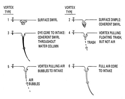
Above: Figure 3: Alden classification of free surface vortices
TEST PROGRAMS
Test programs and matrices are generally customized to specific requirements of the subject study. Tests for selected operating conditions are conducted at scaled flow and submergences. For flows of interest, the water level is allowed to drop at the rate corresponding to that in the field (as governed by the flow until the onset of air entrainment is identified for that flow). As the water level drops, a simultaneous record of flow and water level versus time is logged and the onset of air entrainment is observed and recorded with a video camera. Simultaneously, additional video cameras record the onset of air bubble ingestion into the suction pipe as observed through the acrylic section of the suction pipe. Free surface vortices are classified from type 1 to type 6 (see figure 3). Of particular interest for studies such as these are air drawing vortices (type 5 and 6). Air may also be ingested into the suction pipe due to local draw down of the water surface as water levels approach suction nozzle entrance.
Upon completion of initial testing, results are then evaluated to determine the need for modifications such as vortex suppressors which would allow for additional water level draw-down. With modifications installed, testing is repeated to determine the effectiveness of various devices in suppressing objectionable vortices and air entrainment.

Figure 4. McGuire Nuclear Power Station. RWST’s are circled in red. Photo courtesy of North Carolina Division of Water Resources
A CASE IN POINT: DUKE ENERGY’S MCGUIRE STATION
Duke Energy’s McGuire Nuclear Power Station is located in Huntersville, North Carolina. McGuire desired to perform scale model testing to proactively address the generic issues identified by the NRC 2006 informational notice. The primary objective of the scale model testing was to demonstrate that their original RWST vortex allowance had been conservative. The performance of a detailed physical model study could also provide additional ECCS sump inventory margin in the event of a Loss of Coolant Accident (LOCA), and determine whether or not a vortex suppression device would be necessary for the RWST. A model was constructed using a geometric scale of 1:4.073.
Testing included transient water level conditions simulating the field operation for selected flows (corresponding to prototype flows of 1,600 to 19,700 gpm) and water levels giving submergences of 1 to 5 ft above the suction nozzles in the model (prototype submergences of 4 to 20.3 feet).
Results showed that the submergence at the onset of air entrainment ranged from 0.049 to 0.705 feet prototype for flows ranging from 1,600 to 19,700 gpm prototype, respectively. Onset occurred at water levels far below Hydraulic Institute guidelines for all cases. Based on these test results, it was determined that a vortex suppression device was not required for the McGuire RWST, as the expected water levels during operation would be higher than those indicated for onset of air entrainment for a given flow. In addition to sparing Duke Energy the modest materials and engineering costs of such a device (approximately $50,000 per unit), the more appreciable savings was associated with reduced outage time and resources.
SUMMARY
Several US Nuclear Power Stations have been required to take corrective action to address the potential for vortex induced air entrainment associated with flow withdrawal from certain types of water storage tanks. Although some guidance exists in the literature to estimate vortex formation and air entrainment under steady-state operating conditions, the potential for the phenomena under transient water level draw down conditions is not well understood.
Further, the potential for occurrence under these transient conditions is strongly influenced by inlet suction geometry and orientation, the presence or absence of vortex suppression devices, and the proximity of obstructions inside the tank to the suction pipe inlet. A scaled physical model test program can demonstrate whether current vortex allowances are conservative and, if not, what mitigation measures are likely to resolve the problem. ◆
SOURCES
Daggett, L. & Keulegan, G.H., “Similitude in free-surface vortex formations,” J. of the Hydraulics Division, ASCE, November, 1974.
Harleman, D.R.F., Morgan, R.L. & Purple, R.A. 1959. “Selective withdrawal from a vertically stratified fluid,” 8th Congress of the International Association for Hydraulic Research, August 24 – 29, Montreal, Canada.
Hydraulic Institute Standards, American National Standard for Pump Intake Design, ANSI/HI 9.8-2012.
JPGC2001/PWR-19010, “Air Entrainment in a Partially Filled Horizontal Pump Suction Line,” June 2001.
Padmanabhan, M. & Hecker, G.E., 1984. “Scale effects in pump sump models,” ASCE J. Hyd. Eng. 110, N. 11, November, 1984
For More Information:
Andrew Johansson is the director of hydraulic and numeric modeling at Alden Research Laboratory and is on the intake design committee of the Hydraulic Institute (HI). Dr. Mahadevan Padmanabhan, P.E. is a senior consultant and former principal at Alden Research Laboratory and has published widely on nuclear power plant thermal hydraulics and performed generic testing to determine flow characteristics in emergency core cooling system (ECCS) containment sumps (NUREG/CR2758), data from which was subsequently used to revise the NRC regulatory guidelines. Founded in 1894, Alden is the oldest continuously operating hydraulic laboratory in the United States and one of the oldest in the world. Alden has been a recognized leader in the field of fluid dynamics research and development with a focus on the energy and environmental industries. For more information, visit www.aldenlab.com.
____________________________________________
MODERN PUMPING TODAY, July 2016
Did you enjoy this article?
Subscribe to the FREE Digital Edition of Modern Pumping Today Magazine!
![]()


