


Safety relief valves are essential for safeguarding industrial systems, equipment, and personnel from the hazards of overpressure. Serving as a fail-safe mechanism, these valves automatically release excess pressure once it surpasses a predetermined limit. By doing so, they not only prevent equipment damage and costly downtime but also reduce the risk of catastrophic incidents such as leaks or explosions.
These valves are indispensable across industries like oil and gas, chemical processing, power generation, and manufacturing. Designed for applications involving steam, gas, and liquid processing, safety relief valves ensure safe operations while preserving system integrity and reliability.
Selecting the right safety relief valve (SRV) is crucial for system safety, compliance, and efficiency. Beyond basic design, factors like trim materials and valve body composition play a key role.
Safety Relief Valves (SRVs) are a highly regulated product category, engineered to comply with stringent industry standards like ASME Section VIII / XIII, API 526, and ISO 4126. These standards ensure both safety and reliability in their operation.
Despite these regulations, SRVs can differ significantly in performance, durability, and maintenance needs. Some models are built with advanced materials to withstand extreme conditions, incorporate cutting-edge sealing technology to enhance repeatability and prevent leaks, and feature streamlined designs that minimize the need for excessive spare parts.
VERSATILITY
Safety Relief Valves (SRVs) are highly versatile devices designed to meet a wide range of pressure management needs. They can operate as either a Pressure Relief Valve (PRV) or a Relief Valve (RV), depending on the specific application requirements. This flexibility eliminates the need to choose between the two, offering an adaptable and efficient solution.
Pressure Relief Valves (PRVs) are engineered to open when excess pressure builds up, safely releasing it to restore normal levels before closing to prevent further flow. On the other hand, Relief Valves (RVs) use a spring-loaded mechanism that responds to static upstream pressure, making them particularly effective for handling incompressible fluids.
By combining the strengths of both PRVs and RVs, Safety Relief Valves provide a reliable, streamlined option. They simplify system design by reducing the need for multiple components, ensuring efficiency and adaptability for a variety of applications.
SIMPLICITY
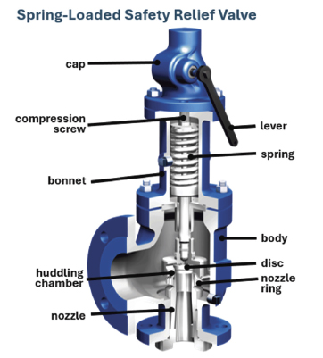
The spring-loaded safety valve, the subject of this article, is the most widely used and trusted type of safety release valve. Its straightforward design, proven reliability, and cost-efficiency have made it the go-to choice across various industries. Simple to install and maintain, these valves deliver effective and dependable pressure relief, making them well-suited for most systems. Their versatility and consistent performance position them as the ideal solution for a wide range of demanding applications.
An alternative design, Pilot-Operated Safety Relief Valves (POSRVs). are engineered for specialized, high-pressure scenarios that require exceptionally precise control. Although they perform reliably under extreme conditions, their complex design includes additional components that require more maintenance and extra parts. Furthermore, the small orifices and connecting lines increase their vulnerability to issues like contamination and clogging.
For most applications, direct spring-loaded valves remain the preferred choice due to their reliability, simplicity, lower cost, and minimal maintenance requirements.
PRINCIPLES OF OPERATION
Spring-loaded safety relief valves include a nozzle threaded into a cast body housing, flanged to a pressurized system. A disc is held against the nozzle by a spring contained in a cast bonnet, which may or may not be pressure-containing, depending on the application.
The spring is adjusted with a compression screw to calibrate the opening or set pressure. A cap is placed atop the bonnet and comes in various designs, including gastight caps that prevent leakage and others that either restrict access or safeguard the set pressure adjustment screw. The cap may contain a lifting lever, allowing the valve to be operated manually.
An adjusting ring threads onto the nozzle to regulate the geometry of the fluid exit control chamber, also known as the huddling chamber. The huddling chamber essentially functions as a second orifice. The design of this chamber plays a crucial role in managing valve opening and closing pressures, as well as ensuring stable and efficient operation.
During normal operation, the valve stays closed because the spring force (FS) exceeds the system pressure on the nozzle seating area (PA). When the pressure rises enough to balance these forces, the set pressure is reached, the disc lifts and fluid flows through the valve. Once the pressure drops to a safe level, the valve closes.
Just before reaching set point, the safety relief valve leaks fluid into the huddling chamber. The fluid now acts on a larger area of the disc inside the huddling chamber, causing the valve to experience an instantaneous increase in the opening force. Pressure on this larger area rapidly opens the valve.
Although the opening is rapid and dramatic, the valve does not open fully at set point. System pressure must rise above set point to reach full lift and flow capacity. Maximum lift and certified flow rates are achieved within the overpressure limits set by codes and standards. Safety relief valves are designed to allow overpressure to reach full rated flow, which can range from 10 percent to 21 percent for unfired vessels and systems, depending on sizing, number of valves, and fire conditions.
Once the valve controls the pressure excursion, system pressure begins to decrease. The huddling chamber regulates fluid flow, so system pressure must drop below the set point for the spring to close the valve. The difference between set pressure and closing pressure, called blowdown, is usually expressed as a percentage of set pressure.
A LOOK AHEAD
Next month, we’ll conclude this series by taking a detailed look at the components that you should be familiar with when assessing these indispensable valves, from nozzle design to seat types and advanced seat features to balanced bellows. We’ll also walk through some of the basics when handling challenging media.
ARI can look back on a tradition of more than sixty years as a partner for control, isolation, safety and steam trapping of liquid and gaseous media. ARI-Armaturen USA, the North American branch of ARI, was opened in Texas in 2004 to supply customers in the United States, Canada, and Mexico. As an efficient partner offering a wide range of products with custom product solutions, a production facility fitted with the most up to date technology and a local comprehensive customer service, success came quickly. For more information, visit www.ari-armaturen.us.