Lowering maintenance costs and extending wastewater treatment pump product life is a key concern of any operator. Here we review some design considerations that contribute to lowering costs for progressing cavity pumps in wastewater treatment plant applications, including speed, drive configuration, sealing options, joint types, and piping systems. We also discuss pump configuration options that can contribute to cost reductions or minimize maintenance.
DESIGN IS FUNDAMENTAL TO CONTROLLING COSTS
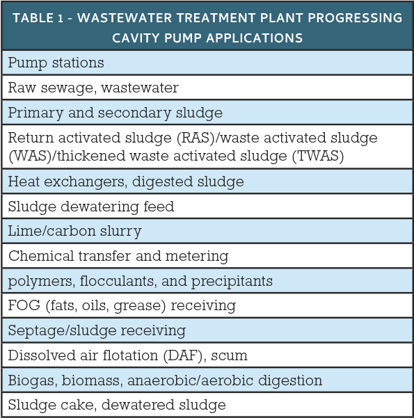
Table 1 is a summary of the wide variety of potential wastewater treatment plant pump applications. Picking the right design for the specific application is critical for ensuring the pump (and the overall system) is going to operate properly. This will in turn be the major influence on the overall cost of ownership (COO).
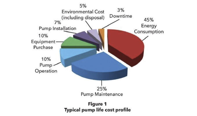
Much of the cost is determined by the initial system design and pump technology selected. A common rule of thumb suggests that about 80 percent of overall equipment life costs (maintenance, operation, and Energy consumption) has to do with the initial design of the overall plant and process equipment/pumps used. In other words, whatever is designed comes with a set amount of fixed costs. Therefore, selecting the right equipment (in terms of size, technology, and options/features) will have a major effect on costs; selecting the wrong equipment will result in higher costs and more downtime. Another 10 percent goes to environmental costs (disposal), installation, and downtime. This leaves approximately 10 percent for the initial purchase of the pump.
There are several progressing cavity (PC) pump configurations that can be used for these applications. Each has advantages and disadvantages, and some are more appropriate than others for a particular application. PC pumps can run a long time without service, but when needed, the service required can depend on the design and options selected for the pump. Joints, access windows, type of seal, stator design, rotor materials and coatings, bearings, and ancillary equipment around the pump impact service. Ultimately the pump needs to be designed for minimal and easy servicing.
When one examines the total cost of ownership, including the initial cost of purchase, the electricity used, parts, and maintenance, what looks like a lower cost option may actually end up being the higher cost option. Reduction of service frequency, reduction of required pump parts, and easier, faster serviceability are critical attributes for pump selection. Focusing on these particular areas and spending a little bit more money upfront, will pay dividends.
PUMP DESIGN CONSIDERATIONS
Most operators will work in collaboration with an engineering firm to select and size the right equipment. Keeping in mind that the correct design is important for reducing costs, operators should consider the following factors when selecting a PC pump. Each one has its own positive and negative impact.
Speed
The faster you run the pump, the faster it will wear and the more frequently service will be needed. In other words, greater speed = exponential wear. However, a fast pump usually means a smaller footprint and lower upfront cost (but you pay on the back end with more repairs). Slower is usually better for most applications.
Drive Configuration
The key issue is how much space is available for the pump. PC pumps are long in nature. Adding a bearing frame adds more length, but provides a robust drive shaft supported by independent bearings to handle the thrust load of the pump. This is the force (axial load) pushing the opposite direction from flow across the centerline of the pump. This is essentially what the pump undergoes as it pumps against the system backpressure. Whereas the direct drive is shorter and for low pressure and is sufficient for many applications.
Typically bearing frames are used when the need for high pressures exceeds direct drive capabilities, when the desire for easier servicing is required, or when a belt configuration for space restraints is preferred. Piggyback/overhead or L-shaped bases can shorten the installation footprint. Vertical mounting of the pump can also accommodate limited space.
Viscosity
The thickness of fluid limits the pump speed, suction, discharge piping ID, and pipe length from the pump by significantly influencing the design and the pressure losses of the system. This affects the suction side or the NPSHa (net positive suction head available) for the pump. Pumps have a specific amount of head pressure required to operate correctly. Otherwise, the result is cavitation and potential failures.
Pump Rotor and Stator Geometry
For the most part, two geometries dominate the various applications. For simplicity’s sake, we will call them low flow/high pressure and low pressure/high flow. Both have their own inherent ratings for NPSHr (net positive suction head required) based on the pump’s internal design. There are other geometries that can provide higher flow at higher pressures and another for higher flow at lower pressures. Typically, you trade off flow for pressure and vice versa.
Number of Stages
The maximum discharge pressure and ultimately the pump rating per stage is determined by the number of stages. Typically, each stage is rated for 90 psi (6 bar). Therefore, two stages would be rated for 180 psi (12 bar) and so on. Adding more stages for a given rated pressure divides the pressure affecting each stage. More stages equals lower pressure per stage and allows for longer life. With most applications in WWTPs, there is abrasion. Abrasion comes from grit and other inorganics (as well as some organics), that cause wear over time on the pumping elements. This wear is to be expected; it is normal to de-rate the pressure per stage due to the amount of anticipated wear. For example, pumping polymer is very lubricating, has no abrasion factor, and can be rated for the maximum capability of the pump. As another example, 1-2 percent sludge may only be derated by 20 percent per stage (90 psi x 80 percent = ~70 psi) making the rated discharge pressure 70 psi or less. Finally, if you were to pump cake (20 percent or higher), each stage would need to be derated to 50 percent or more.
Stator Design
The design of the stator can help facilitate faster and easier replacement. Each stator inherently uses compressive forces in the design that compresses around the outside of the rotor; which in turn creates the sealing line of the pumping elements. These compressive forces are what make the pump work. However, they also make it harder and more time consuming to replace the stator with a new one.
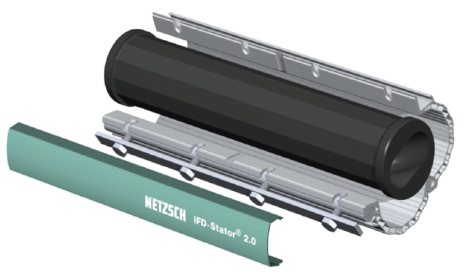
A new stator requires a great amount of force to install. Netzsch offers a time-saving stator replacement option. The iFD-Stator® design allows for the compressive forces to be released/removed during installation (and removal). Unbolting the compressive shell releases the axial and radial compression of the stator on the rotor. This allows for the new stator tube to slide on with relative ease and then be clamped down without the need for extra turning forces (see figure 2).
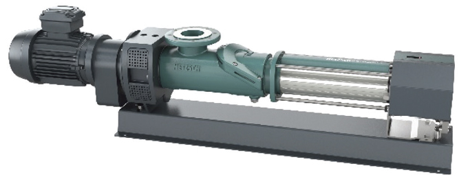
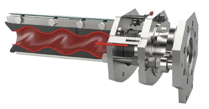
Money-saving stator adjustments can also compensate for wear, using compression to re-establish the stator sealing line, increasing operational life and bringing the stator back to factory performance. The process can extend stator life of up to six times. This is a boon to operators, who would otherwise have to take the pump out of service, shut down the entire process, and lose all the revenue from that train. While standard stator replacement may take as much as six hours, with the Netzsch xLC® (stator adjustment device) attached to a pump, it takes less than two minutes (while pumping or not) the stator can be easily adjusted/tightened to renew the performance back to factory standards (see figures 3 and 4).
A LOOK AHEAD
In next month’s conclusion to this series, we’ll take a deep dive into the various materials of construction compatibility as well as concerns over solids handling and fluid media size. We’ll conclude with a detailed examination of serviceability option.
Jeffrey Bye is municipal director for Netzsch Pumps USA. The Netzsch Group is an owner-managed, international technology company with headquarters in Germany. The Netzsch business units Analyzing & Testing, Grinding & Dispersing, and Pumps & Systems represent customized solutions at the highest level. More than 4,000 employees in thirty-six countries and a worldwide sales and service network ensure customer proximity and competent service. For more information, visit www.netzsch.com.


