


Part 3 of a 3-Part Series In the first two parts this series, we looked at many of the ways in which pumps can be mounted as well as some of the “Best-in-Class” users’ decisions as well as an important exception to the general guidelines for secure-in-place installation. In this final installment, we will discuss the best-practice specifications for alignment jacking provisions and conclude with an adaptable checklist for base plate installation options and guidelines. Of course, no installation checklist can cover the entirety of pump users’ experiences and specifications, but some concerns remain worthy of attention in the majority of applications.
ALIGNMENT JACKING PROVISIONS
A best-practices specification will include smart alignment jacking provisions. Note figure 6, where the purchaser specified an arrangement that allows insertion (and later removal) of alignment jacking tabs in the x and y-directions next to each of the four motor feet.
Figure 6 Removable alignment jacking tabs shown inserted in three of four locations next to the two motor feet shown here (source: Stay-Tru®, Houston, Texas)
Portable jacking tabs, figure 6, (inserted in a welded-on bracket) allow driver alignment moves to be made. Thereafter, the jacking bolts are backed-off and the entire tab is removed. In careless installations jack screws are sometimes left tightened against the motor feet. In those instances, motor heat and thermal growth might force the feet into these bolts even more, which could cause the entire motor casing to distort (see reference 4). Note, therefore, that backing-off jacking bolts should be one of many installation checklist items.
If epoxy-filled base plates are part of the package, pumps and drivers can indeed be mounted and aligned before the set is shipped. However, before installing a conventional base plate, the pump and its driver must be removed from the base plate and set aside. Leveling screws are then used in conjunction with laser-optic tools or a machinist’s precision level. With the help of these tools the base plate mounting pads are brought into flat and parallel condition side-to-side, end-to-end, and also diagonally. This takes time and skill.
After installing an epoxy-filled base plate and leveling it, an epoxy grout cap should be placed on the foundation top. Some of this epoxy grout should flow into the space between the foundation and the perimeter of the monolithic base plate. There will be no incentive to fill the entire space and the area of support desired is calculated such that this epoxy grout is loaded to perhaps 50 psi compressive pressure. As an example, a 72 by 24 inch (1830 by 610 millimeter) epoxy-filled base plate would have a 192-inch (4880 millimeters) perimeter. Grout supporting a 4-inch (100 millimeter) width would constitute an area of approximately 800 square inches. If the total weight of the pump set is, say, 12,000 pounds, the pressure load would be 12,000 / 800 = 15 psi—well within 50 psi.
By its very nature, pre-filling a base plate will greatly reduce problems of entrained air creating voids. However, because grout materials are highly viscous, proper placement of the epoxy is still important to prevent air pockets from developing (see reference 5).
Outsourcing base plate design, fabrication and pre-filling with epoxy grout has often been found economically attractive. Figure 7 shows it ready for shipment.
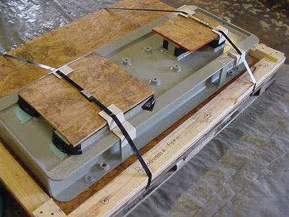
Figure 7 Removable alignment jacking tabs shown inserted in three of four locations next to the two motor feet shown here (source: Stay-Tru®, Houston, Texas)
Conventional grouting methods for non-filled base plates, by their very nature, are labor and time intensive (see reference 3). Utilizing a pre-grouted base plate with conventional grouting methods helps to minimize some of the cost, but the last pour still requires a full grout crew, skilled carpentry work, and good logistics. To further minimize the costs associated with base plate installations, a new field grouting method has been developed for pre-grouted base plates. This new method (see reference 4) utilizes a low viscosity high strength epoxy grout system that greatly reduces foundation preparation, grout form construction, crew size, and the amount of epoxy grout used for the final pour.
WHAT WE HAVE LEARNED:
PARTIAL CHECKLIST OF FOUNDATION AND BASE PLATE TOPICS
Use ultra-stiff, epoxy-filled formed steel base plates (“StayTru®” method or an approved equivalent) on new projects and on optimizing existing facilities
a) Proceed by first inverting and preparing the base plate; use recommended grit blasting and primer paint techniques
b) Fill with suitable epoxy grout to become a monolithic block
c) Allow to cure; after curing, turn over and machine all mounting pads flat and co-planar within 0.0005 inch per foot (0.04 millimeters per meter).
d) Next, install complete base plate on pump foundation. Anchor and level it within the same accuracy.
e) At final installation, place epoxy grout between the top of the foundation and the space beneath the monolithic epoxy pre-filled base plate
On welded base plates, make sure that the welds are continuous and free of cracks.
On pump sets with larger than 75 kW drivers, ascertain that base plates are furnished with eight positioning screws per casing, i.e. two screws (“jacking bolts”) per mounting pad.
a) These positioning screws could be located in removable tabs (i.e., tabs slipped into a welded guide bracket) or fixed tabs (i.e., tabs welded onto the base plate).
b) Pad heights must be such that at least 1/8 inch (3 millimeters) stainless steel shims can be placed under driver feet.
Conventional base plates must be installed and grouted on foundation with pump and driver removed. Only then should pump and driver be re-installed and leveled.
Full epoxy and/or epoxy pre-filled steel base plates can be installed and grouted on a foundation with pump and driver already aligned and bolted down on the base plate. ■
REFERENCES
Bloch, H. P., and A. R Budris. Pump User’s Handbook: Life Extension, 4th Edition (2013). Fairmont Press (ISBN 0-88173-720-8).
Bloch, H. P., and F. K. Geitner. Major Process Equipment Maintenance and Repair, 2nd Edition. Gulf Publishing Company (ISBN 0-88415-663-X).
Bloch, H. P. Pump Wisdom: Problem Solving for Operators and Specialists (2011). John Wiley & Sons (ISBN 978-1-118-04123-9).
Monroe, Todd R. and Kermit L. Palmer. “Methods for the Design and Installation of Epoxy Pre-filled Base Plates” (1997 Marketing Bulletin). Stay-Tru® Services, Inc., Houston, Texas.
Barringer, Paul, and Todd Monroe. “How to Justify Machinery Improvements Using Reliability Engineering Principles,” Proceedings of the Sixteenth International Pump Users Symposium (1999). Turbomachinery Laboratory, Texas A&M University, College Station, Texas.
ABOUT THE AUTHOR
Heinz P. Bloch, P.E., is one of the world’s most recognized experts in machine reliability and has served as a founding member of the board of the Texas A&M University’s International Pump Users’ Symposium. He is a Life Fellow of the ASME, in addition to having maintained his registration as a Professional Engineer in both New Jersey and Texas for several straight decades. As a consultant, Mr. Bloch is world-renowned and value-adding. He can be contacted at heinzpbloch@gmail.com.
MODERN PUMPING TODAY, July 2014
Did you enjoy this article?
Subscribe to the FREE Digital Edition of Modern Pumping Today Magazine!