


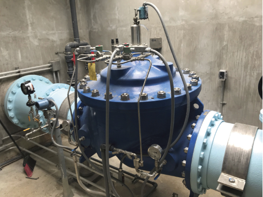
The most common and effective solution to mitigate excessive pressure and manage leakage in a water distribution system is the Pressure Reducing Valve (PRV). These ingenious devices have proven to be indispensable assets, offering a straightforward and effective means to transform problematic high-pressure sources into controlled, fixed outlet pressures, seamlessly adapting to varying flow demands.
While PRVs are highly effective, it is important to acknowledge that they alone cannot eliminate leakage. Water utilities still need to be proactive in identifying and repairing leaks throughout the network. When pressures are at their peak, leaks are also at their peak. The strategic installation of PRVs can maintain system pressures within serviceable levels, which can significantly reduce water loss through leakage and mitigate the potential for new leaks.
By combining PRV installations with proactive leak detection and repair initiatives, water utilities can achieve optimal pressure management. This holistic approach not only mitigates transient events and maintains network integrity but also minimizes non-revenue water (NRW) loss due to leakage, fostering a more sustainable and efficient water distribution system.
FIND THE RIGHT LOCATION FOR YOUR PRV
Before a PRV is selected it is important to gain as much information as possible about the distribution network the valve will be servicing. The following outlines the elements that need to be considered in choosing the correct PRV and location.
- Determine a zone or District Metered Area (DMA) that the PRV will feed into and ensure that the zone can also be monitored.
- How many properties or connections fall within the zone? Identify the areas that suffer the lowest pressure. This is usually the property or properties located at the highest altitude or the furthest away from the water source, or perhaps it’s a low-pressure area due to poor infrastructure. This is called the Critical Point or Critical Node (C.P.)
- Determine where the PRV will be located.
- Ensure this new zone can be serviced through a single pipe source and all interconnecting boundary valves must be closed off.
- At the point of entry into the zone, a flow meter must be installed allowing flow readings to be taken of water entering the zone. (Typically, the flow meter will be located close to or integrated with the PRV).
COLLECTING DATA FROM THE DMA
Once the zone has been defined, the most crucial element is data acquisition. Both flow and sometimes valve position must be logged and data collected over time to gain intelligence and understanding of how the new zone operates hydraulically under various flowing conditions. These newly defined zones are referred to as DMAs or Demand Management Zone.
It is recommended to collect the following data:
- Flow rates: through the single feed into the area
- Pressure: where the PRV is to be located (near DMA Flowmeter)
- Pressure point in the network that suffers from lowest pressure – C.P.
- Pressure at zone boundaries
Once you have the above data you can determine the average flow rate into a DMA, for example:
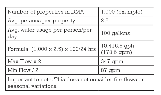
USING THE DATA
Once the DMA data has been collected for a sufficient time frame (minimum seven days plus incorporating fire flows and seasonal variations), the data can be analyzed and will begin to provide the hydraulic characteristics of the area.
The collected data will show the variation in inlet pressure and flow into the DMA. The critical point pressure data will vary throughout the day/night as a result of the dynamic head losses caused by fluctuations in flow demand across the network.
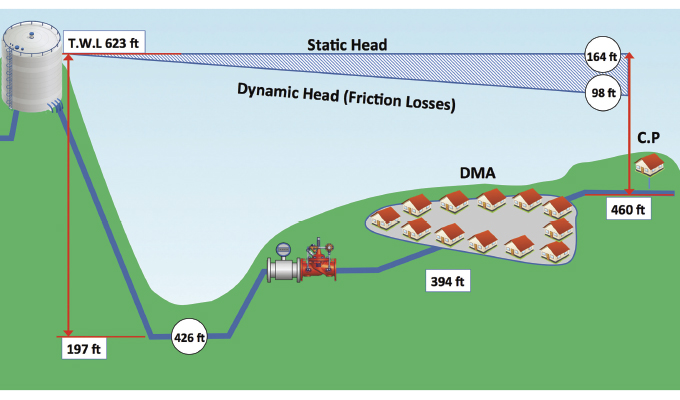
Figure 2 shows the hydraulic gradient of a typical water supply network at maximum flows. The top water level in the service reservoir provides the head of pressure into the pipe system and the topography of the pipework shows the height of the DMA and Critical Point, but more importantly the resulting pressure at the Critical Point due to the friction losses along the pipeline.
These friction losses will vary and increase as flow demand increases through the network. This is caused by many factors including, pipe age, condition, and size variation across the network but also an increase in flow velocity.
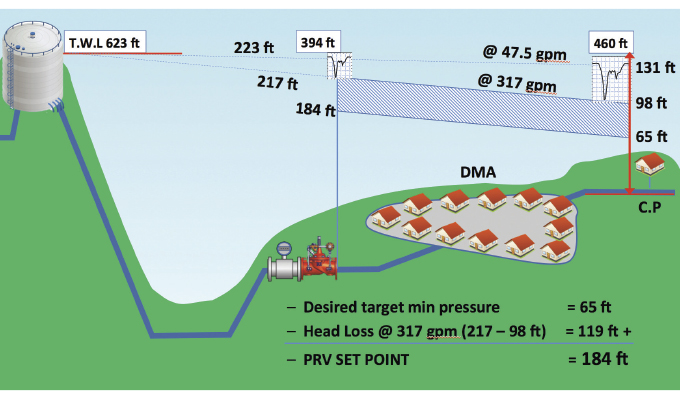
Figure 3 represents the new hydraulic gradient after the PRV has been installed and set at the desired outlet pressure. The Critical Point has been protected so that the minimum pressure at the maximum flow will not drop below 65 feet. It is common practice to drop outlet pressure in stages over a period of time while continuing to monitor the CP and reduce the potential for customer complaints during this process.
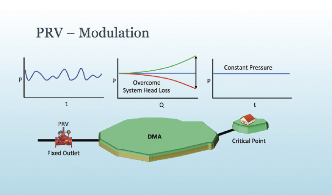
PRESSURE MODULATION
Understanding the hydraulic characteristics of the network and installing a PRV to a fixed outlet pressure can save leakage up to around 70 percent. Although this is an impressive payback, the water industry is looking for new and innovative ways to reduce this figure further. To achieve this, PRVs can be modified to modulate the outlet pressure according to changes in flow or time. Understanding the hydraulic gradient across the DMA and looking for differences in PRV outlet pressure compared to the CP pressure is necessary.
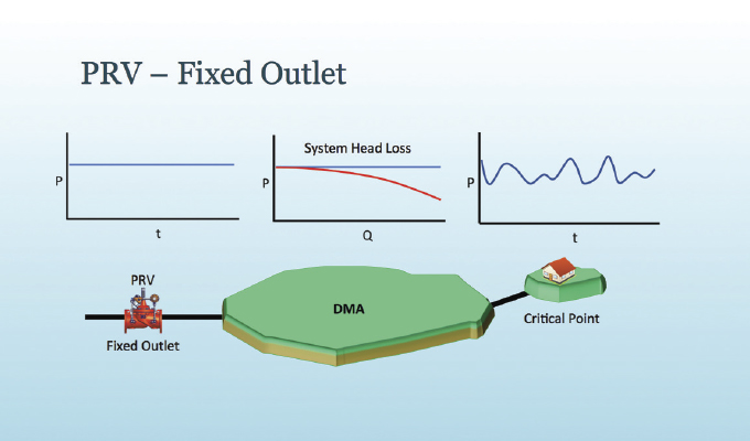
In most cases, a fixed outlet PRV is set to protect the minimum pressure requirements at the CP at peak flow demand. Any other time the system is not in full demand the PRV provides excessive pressure, this can be a huge percentage over twenty-four hours, particularly at night when the system is at its lowest flow demand. The term ‘pressure management’, as far as PRVs are concerned is modulating the outlet pressure to maintain a relatively constant minimum pressure at the CP and overcoming the difference in system head loss.
The solutions can be quite simple to the more complex; two-stage pressure control to complete closed-loop control. In economic terms, this can be quite simple to break down and categorize as providing the most cost-effective solution for the most potential return on investment.
- Small valves (1.5 to 3 inches): Two-stage outlet pressure according to time (night and day) <1500 properties
- Medium valves (3 to 8 inches): Large DMA’s utilizing flow modulation, low or self-powered open loop pressure controllers >1500 properties, usually with upstream pressure (P1) and downstream pressure (P2), flow logging capability and outfitted with communication capabilities.
- Large valves (8 inches and above): Critical PRVs (i.e., trunk main PRVs) closed loop or open loop, sites that have 24VDC and remote comms/ control via SCADA.
Many water utilities prefer simple and inexpensive solutions that can be instituted with little training and support and simply drop the pressure throughout the night. Other utilities prefer a more complex solution such as flow modulation that also provides a means of data logging and the addition of communication. Data acquisition is focussing more on real time data by increasing the frequency of communication to short time intervals, as opposed to a single daily update, providing water utilities with the ability to sustain optimal pressure around the clock.
In some established areas of the world, it is becoming increasingly difficult and expensive to find and benefit from the extra savings of pressure management and the ROI is getting longer. Five years ROI is generally acceptable.
Zones may become ‘rezoned’ for pressure optimization, with more and more small PRVs being installed for those small benefits rather than the expense, support, and maintenance of a full pressure management solution. Essentially, increasing the number of smaller DMA’s.
Many water utilities are investing in smart network solutions where they can interlink DMA’s with intelligent valves and controllers to automatically manage pressures across a much larger scale and where they can build resilience into their networks to protect against issues relating to low water pressure, quick rezoning after pipe bursts, water quality issues, etc.
There can be a substantial knowledge gap in the industry regarding basic hydraulics, network analysis, and the appropriate installation and configuration of PRVs. To bridge this gap, water utilities must collaborate with knowledgeable and experienced control valve partners.
Ryan Spooner manages the technical sales team and is responsible for high-level product and sales support in addition to R&D and product development. His primary focus is centered around the Cla-Val’s electrical product lines interaction with control valves and their deployment for Smarter Water system. Cla-Val is a world-leading designer and manufacturer of automatic control valves. From reducing and relief valves to deluge, air valves and more, Cla-Val manufactures and provides a wide variety of solutions for use in some of the world’s most demanding applications. For more information, visit www.cla-val.com.