


In the second part of this analysis, we hope to demonstrate the real need for a better system to understand and monitor the integrity of gas charged pulsation dampeners and examine the idea of using pulsation monitoring to monitor gas charged dampener integrity during regular reciprocating pump operation. The examination looks at a particular new installation on an offshore platform for Shell. The difficulty and risk in maintaining a safe pump system with these dampeners is magnified in offshore and unmanned equipment operations.
Until better options appear on the market to address these important issues, pulsation monitoring is a technique that can be used to monitor dampener integrity. However, when using pulsations as the monitoring strategy several important considerations must be taken into account.
DAMPENER MODELING APPROACH
When a pulsation dampener loses charge, or fails, pulsations will increase. The initial monitoring concept was when pulsation levels increase past a limit, send an alarm to the control system indicating to operations that the dampener has failed. The concept is simple, but the reality in this case was actually very complicated.
The System
The pump system under analysis was for two triplex diaphragm condensate pumps, operating in parallel across a variable speed range of 37 to 120 revolutions per minute (pump speed). The pump flow conditions were forecasted from reservoir data and had expected yearly changes in flow and differential pressures from years 2012 up to 2020. The large speed range of these pumps would present significant challenges to the activities of this project.
The Pulsation Model
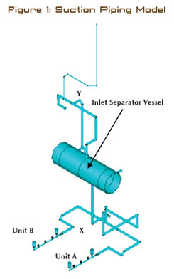
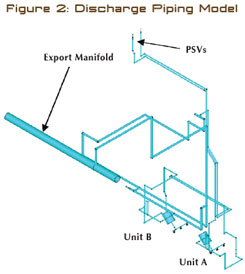
A pulsation model was created for the initially designed system including the two pumps, off-skid rack piping between the pump skid and inlet contactor vessel, and the main discharge export manifold using Beta Machinery Analysis (Beta)’s proprietary, non-linear, fluid dynamic modeling software. See figures 1 and 2 for images of the suction and discharge system pulsation models. The model input to the piping system involves the calculation of pump performance and the actual pressure profile of the fluid versus time of each fluid end of the pump. Each fluid end has its own input into the piping system per rotation of the crankshaft, since each end travels to outer dead center 120 degrees out of phase with the other. This creates the tendency of a triplex pump to have the highest pulsation input at the third order (3x—three events per rotation), and multiples of three, into the piping. This is typically referred to as plunger passing frequency (PPF). So if you collect frequency domain pulsation or vibration on piping around a triplex pump, you should see excitation at three times rotational speed of the pump (or PPF) and multiples thereof.
The pulsation analysis was conducted with the piping system and dampeners as proposed. Results were compared to API 674 (Third Edition) guidelines and Beta’s unbalanced shaking force guidelines. The initial results found that there were pulsation guideline violations at several locations within the piping at PPF and twice PPF, and high unbalanced forces were predicted in the suction header and discharge PSV and bypass lines, all at various pump speeds. Cavitation was also predicted to occur in the suction system. Modifications were required.
The pump OEM bid for this project included the preliminary sizing of a pulsation dampener for the suction and discharge side. The dampener was sized for a given volume using standard rule of thumb calculations based on the concept of acceleration head. Dynamic pressure or pressure pulsation in pump systems has historically been referred to as acceleration head. A common misconception is that sizing pulsation control devices for pumps using acceleration head sizing calculations is equal to an API 674 pulsation study. This is not the case.

Calculating Acceleration Head
Calculation of acceleration head is a technique whereby the pressure fluctuation is estimated by simplifying assumptions and empirical techniques. Acceleration head calculations cannot take into account acoustical resonances in a piping system. Acoustical resonances can result in very high pressure pulsations because of the low damping and high amplification of pulsations at resonance. A computer model that calculates the acoustical properties of the piping system as well as non-linear pressure and flow fluctuations is required to accurately determine the suction system pressure pulsations. Acceleration head calculations are not as effective at characterizing pressure pulsations as a pulsation computer model. This is illustrated by the initial results of the pulsation analysis as originally designed, stated earlier.
The suction system with the initial designed acoustic dampener had several areas of acoustical resonance causing cavitation and high unbalanced shaking forces. Several modifications were attempted including a larger volume pulsation dampener, maintenance-free dampeners, and piping layout changes. The optimum solution included a second pulsation dampener at the blind end of the suction manifold, and modification of the piping such that the manifold connecting the two units was of a symmetrical design.
The wide speed range of this pump, combined with acoustical resonances within the suction piping system required a second pulsation dampener at the blind end of the suction manifold. Two dampeners on one manifold is not a common sight for many pump systems. As such, some description as to why it was required is necessary.
Nodes and Anti-Nodes
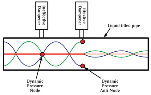
Gas charged pulsation dampeners work upon the principle that pressure surges will be absorbed by the damping of the gas charge within the dampener. When a pump is operating at a fixed speed the pulsation dampener location is an important aspect of pulsation control for pumps. Diaphragm or bladder type dampeners are most effective when placed at a location of maximum pulsation, known as a pressure “anti-node.” If the dampener is placed at a “node” location (where there are low pulsations in the piping standing pressure wave), the dampener will do nothing at all. This is where the problem lies in variable speed installations. The locations of nodes and anti-nodes in the piping change with speed. This means if you have a pulsation dampener at a fixed location, it will be effective for a narrow range of speeds, and ineffective at most of the other speeds of the pump. This was the case for this pump system.
Additional Pulsation Dampeners
One of the ways to increase the effective speed range of the dampening system is to add another pulsation dampener at a different location. In this case the second dampener was installed at the blind end of the suction manifold for a few reasons. A common phenomenon when placing a dampener near the inlet or outlet of the manifold is the creation of a quarter wave resonance between the dampener and capped end of the manifold. This quarter wave resonance can create high pulsation levels within the manifold piping which interfere with pump valve opening and closing events, and also create high pulsation-induced unbalanced forces on the manifold.
One effective way of reducing this quarter wave resonance is to install a second dampener at the capped end, which has the added benefit of increasing the effective speeds that the pulsation dampening system can handle.
The discharge system utilized a maintenance-free liquid filled dampener at the manifold outlet. Even with the maintenance-free dampener, quarter wave resonances were found in the bypass piping for both units, and pulsation forces within the relief valve piping exceeded guideline. Modifications included shortening the bypass piping by relocating the valves, and adding extra clamp supports to the relief valve piping to withstand the marginal forces.
CASES FOR INVESTIGATION
Since two gas charged dampeners were required for the suction system, the investigation into the dampener integrity control system involved four pulsation cases:
- Case 1: Both dampeners functioning
- Case 2: Manifold inlet dampener fails
- Case 3: Manifold blind end dampener fails
- Case 4: Both dampeners fail
Once an acceptable pulsation solution was found for the suction system, a simulation of each case was conducted to determine how best to set up the dampener integrity monitoring system. A monitoring system for the discharge was not needed since gas charged dampeners were not used.
THE RESULTS
A detailed study of pulsation levels in the piping system throughout the speed range was completed at locations where a clear difference could be seen in pulsation levels to determine the state of the dampener. Each case was simulated by removing the gas volume within the dampener. The results were found to be highly dependent on speed of the pump. Two locations were better for finding a significant difference in pulsation levels between failure cases. The locations are highlighted in figure 4. The pulsation levels predicted at location 1 provide better indications of failure of the manifold inlet dampener. Pulsation levels predicted at location 2 provide better indications of failure of the manifold blind end dampener.
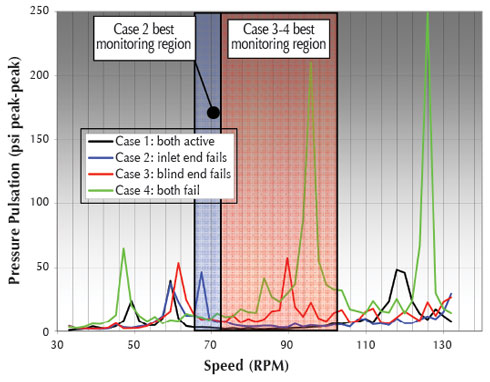
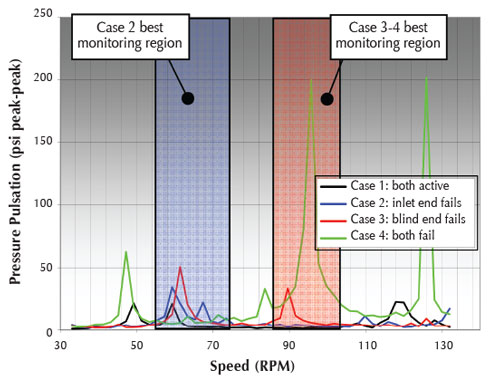
Figure 5 shows the pulsation amplitudes of each of the four cases throughout the speed range for transmitter location 1. Pulsation amplitude is plotted verses pump speed (rpm) for each of the cases. It can be observed from figure 5 that monitoring for failure of the stabilizers for cases 3 and 4 is best between 75 to 100 revolutions per minute. The relative pulsation amplitude between case 1 and cases 3 and 4 provides a margin of difference for a control system to monitor. The highest relative amplitude difference between cases 1 and 2 occurs at the narrow range of 63 to 69 revolutions per minute. Case 2 pulsation levels are marginally higher than case 1 from 70 to 100 revolutions per minute but not by a significant difference. Both regions are highlighted with shaded boxes.
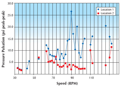
Similar to figure 5, figure 6 shows the pulsation amplitudes of each of the four cases throughout the speed range for transmitter location 2. It can be noted that the monitoring region (in terms of speed range) for case 2 is wider for transmitter location 2, than for location 1—showing that there is a slight benefit for case 2 detection using location 2 over location 1.
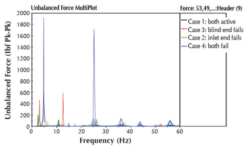
The pulsation-induced unbalanced forces for each failure case in the long vertical suction line between the inlet separator and suction header splitting to each pump (see line X-Y in figure 1) is shown in figure 7. Case 4 of both dampeners failing can result in nearly 1900 pounds pk-pk force shaking the pipe. The next worst case is case 3, which results in nearly 600 pounds pk-pk in the same line. ■
_________________________________________________________________________
ABOUT THE AUTHORS
Jordan Grose is the manager of pump systems for Beta Machinery Analysis. Ravindra Pai is a senior rotating engineer at Shell. For more information, visit www.betamachinery.com. This data was presented in an altered form at Dusseldorf’s International Rotating Equipment Conference in 2012.
_________________________________________________________________________
MODERN PUMPING TODAY, May 2013
Did you enjoy this article?
Subscribe to the FREE Digital Edition of Modern Pumping Today Magazine!
![]()