By Ben Keiser, Applied Flow Technology
As we discussed in the first part of this series, four years ago, the U.S. Department of Energy (DOE) launched the first Energy Conservation Standard for Clean Water Pumps. In part, this is because pumps, fans, and compressors account for about 60 to 70 percent of total electrical energy usage by domestic manufacturers, so these standards are viewed as a starting point for greatly improving pump efficiency and reducing energy costs.
However, though it is good that there are more efforts now for vendors to provide more efficient and energy compliant pumps, as we discussed last month, this is not just about efficiency. With more focus on improving reliability, not only will this minimize repair costs, increase profits, etc., it will naturally improve pump efficiencies as well. Below, we’ll look into how to improve reliability as well as efficiency.
HOW DO YOU IMPROVE RELIABILITY?
Many times, a recommended solution is to incorporate a variable speed drive (VSD) or variable frequency drive (VFD). This can help, but it is more of a band-aid solution. When you see operational problems at the pump, rarely is it due to a faulty pump. Plant maintenance usually ends up fixing issue after issue. But they may not always investigate what is causing the problem in the first place. One example could be a plant wearing through pump seals frequently. After a while, operators may suspect the seals from a certain manufacturer are bad. So, the plant starts switching vendors to find different seals. Most likely, this will only lead to more worn-out seals. If the seal manufacturer asks the plant how they are operating the pumps, most likely it would be found that the seals were never faulty or poor quality in the first place. But it was the pump that killed the seal!
However, what caused the pump to operate at flows away from the best efficiency point (BEP) that would lead to seals wearing out faster? This is where flow analysis software is incredibly beneficial. A system approach with flow analysis is a lot more effective at diagnosing the root cause of the problem than only focusing on the symptom of a problematic component itself.
Here are a few of the many advantages and benefits available when using flow analysis software:
Understand Complex System Interactions Easier
- Multiple load cases
- Seasonal considerations
- Different operating configurations and requirements
- Water hammer and cavitation issues
- Pulsation and resonance problems caused by positive displacement pumps
There are several other key benefits that a flow analysis provides including improved system sizing and scale-up, design feasibility analysis, transient analysis, system troubleshooting, quantify pump/system scaling/fouling/degradation, maintain code compliance, etc.
Overall, lots of money is spent fixing and operating poorly designed systems. The investment in a quality flow analysis software tool will lead to a better system understanding which then leads to better designs and operation. Better designed and operated systems that are well-understood to keep pumps operating as close to BEP as possible will have a major effect on reducing long term costs.

BUILDING A HYDRAULIC MODEL FOR A FLOW ANALYSIS
What information do you need in order to build a hydraulic model for a flow analysis? In general, if there is a hydraulic element in the system that makes an impact on system pressure/flow/temperature, then it should be included in the model. The closer to reality that the system is modeled with as-built system configurations, operating data, valve positions, etc., the more accurate the model results will be. The more accurate the results, the better predictions the model can make when it comes to understanding how various system changes will impact performance.
Here are the basic pieces of information that would be needed for an accurate hydraulic flow model.
- Fluid Properties: Densities, viscosities, vapor pressure, etc.
- Pipes: Inner diameter, friction model (i.e., Darcy-Weisbach, Hazen-Williams, etc.), length, elevation changes
- Tanks: Liquid level, surface pressure, pipe connection elevation
- Pumps: Head curve, efficiency/power curve, NPSH curve
- Equipment: Pressure drop versus flow profile
- Valves: Cv and open percentage data
- Fittings: K factors or equivalent lengths
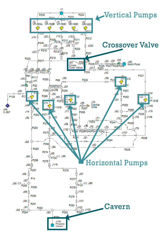
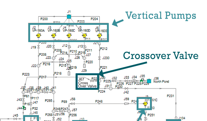
Let’s look at a real-life example of how a system flow analysis had a dramatic impact on improving system reliability and pump efficiency. The hydraulic flow analysis model in figure 2 is for a raw brine injection system that displaced product in a chemical plant’s underground cavern storage facility.
In this system, several of the vertical pumps in parallel were completing hydraulically. Ideally, the flow distribution through each of the pumps should be similar, if not, the same. And in best case circumstances, they would each be operating as close to their BEP as possible. However, when the pumps compete hydraulically, each of the pumps would provide a different flow. Some pumps would dominate and provide more flow than the others. Ultimately, it can cause each of the pumps to operate further away from their BEP.
The pain point for this raw brine injection facility was not high energy costs. They certainly would have had higher energy costs with their pumps operating at low efficiencies. But this was not the problem. This facility dealt with 41 repairs in a five-year period that totaled up to $1.23 million. The MTBF was about fifteen months.
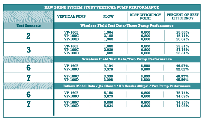
A pump manufacturer was contracted to evaluate pump performance and find ways to improve reliability. After constructing the flow model and calibrating results to measured data, the contractor found that several of the pumps were typically operating between 20 to 50 percent of their BEP. This certainly explains the reliability issues the plant had. Once the model was calibrated, the contractor tested several operating scenarios. This included cases where various combinations of pumps were turned on and off while operating with all valves open, closing off cross-over valves, and maintaining cavern pressures at a certain pressure.
Figure 3 highlights the final results after running over thirty scenarios to determine that only two out of the five vertical pumps needed to operate. This still maintained required system flowrates and dramatically improved reliability where the pumps could operate at 75 percent of the BEP and higher. The simulation discovered better flow paths and pump operation to deliver the same amount of product at required flows and pressures. The simulation improved system reliability and allowed better system recommendations to be made in the future. This is not something that could be accomplished without taking a system approach to a component problem.

CONCLUSION
Ultimately, more attention to pump efficiency is helpful in avoiding wasted energy and reducing energy costs. The new energy conservation standards for clean water pumps will help manufacturers and end users to start purchasing and using more energy-efficient pumps. A deeper focus on reliability and operating pumps as close to the BEP as possible will have a much more dramatic effect on reducing repair and maintenance costs and increasing the MTBF which will decrease downtime and increase profits. And as shown, this effort will naturally improve pump efficiency and reduce energy costs as well. Using a quality flow analysis software tool will streamline the efforts in improving reliability by taking a systems approach to solving operational problems rather than a component by component approach.
FOR MORE INFORMATION
Ben Keiser is technical sales consultant at Applied Flow Technology. With a primary focus on developing high quality fluid flow analysis software, AFT has a comprehensive line of products for the analysis and design of piping and ducting systems. For more information, visit www.aft.com.
MODERN PUMPING TODAY, July 2020
Did you enjoy this article?
Subscribe to the FREE Digital Edition of Modern Pumping Today Magazine!


