By Cliff Knight, KnightHawk Engineering
Crushers and slag grinders are often applied in materials handling and gasification plants to reduce the size of quenched slag from the gasifier’s tap-hole or break clinkers from slow moving bed reactors. These clinkers are typically brittle and relatively easy to crush, but may be larger and very hard and abrasive when sintered during a reactor transient or upset conditions. Also, these crushers are often of toothed roller type, integrated in a pressure vessel subject to charge / discharge cycles, slow rotating yet transmitting very high torques and crushing forces. This makes it simultaneously a “machine” and a “pressure vessel.”
PROBLEM: INTEGRATING ON-SITE NEEDS
A slag breaker dating from the 1970s required replacement. The new design had to incorporate lessons learned in operations and maintenance, fit accurately into the existing structure and inlet-outlet flange face-to-face envelope, and re-use the existing drivetrain. The crusher must reduce slag as well as occasional refractory tiles or bricks, dislodged from the gasifier hot face, to no more than 1 inch in size to avoid bridging and arching in the outlet. The equipment must be designed, manufactured, tested, and delivered to site under schedule constraints, in time for the next scheduled shutdown.
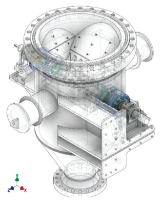
SOLUTION: BRINGING THE DESIGN TO LIFE
KnightHawk engineering digitized hand drawn blue-prints and developed 3D CAD models (below) applied in concept development, client reviews, and manufacturer reviews and design. Detailed 2D CAD drawings and part lists as well as geometry and meshing for Finite Element (FEA) designs, were developed from this model. The pressure vessel was designed as per ASME VIII Division 1 with supplementary analysis by FEA as per ASME/API 579-1 Fitness for Service (FFS) by using the methods and guidelines from ASME VIII Division 2 Part 5.
The rotating parts and breaker element were integrated into the pressure vessel by shaft, breaker tooth, breaker plates, gland seals, end bearings, and a bolt-on cantilever drive unit (not shown) consisting of a motor, gearbox, and coupling. The breaker element is protected from overpower, including an auto reverse, circuit breaker, shear pin, and hydraulic coupling.
The breaker element and teeth must be accurately sized and designed for particle size reduction, throughput and slag crush strength requirements, to ensure effective crushing yet avoid jammed rotor and lockup conditions. KHE determined the required grinding energy by the third comminution theory as per Bond’s equation using a “Work Index” to define motor horsepower, torque, and crushing power requirements as per its experience for this type of equipment.
ACHIEVING SUCCESS
Successful design was achieved by:
- A multi-party, collaborative design process including original OEM Designer, owner-operator, KHE Specialty Engineering, and manufacturers all with significant experience in industry.
- A multi-disciplinary approach including process, mechanical, metallurgical, and controls.
- A multi-physics approach including code “design by rules,” FEA “design by analysis,” first principle machine and structural design by correlations as well as fatigue, thermal, and modal analysis.
This ensured a design fit for purposes and with adequate protection against failure.
PRESSURE VESSEL CONSIDERATIONS
The pressure vessel design must include for considerations of (1) internal pressure-temperature design, (2) fatigue loading from batched feed and pressure cycles, (3) bending and crushing forces from drivetrain weight and work, (4) thermal loading from batch cycles, and (5) modal analysis to ensure no coupling between any fundamental natural frequency, fN, and any of the forcing functions or excitations from the rotating parts result in resonant vibrations.
Materials selection, stainless steel, and tungsten carbide weld overlay of internal surfaces subject to corrosion, impact, crushing, and flow-erosion must be carefully selected to provide a robust yet manufacturable and cost effective equipment fit for service over its design life.
The seal design must include for effective sealing against varying pressure-temperature conditions, a seal flush to ensure cooling, lubrication, and avoid intrusion of abrasive particles. The seal design is schematically shown right. This seal design is typically a multi packing ring compressible gland type with lantern ring assembly.
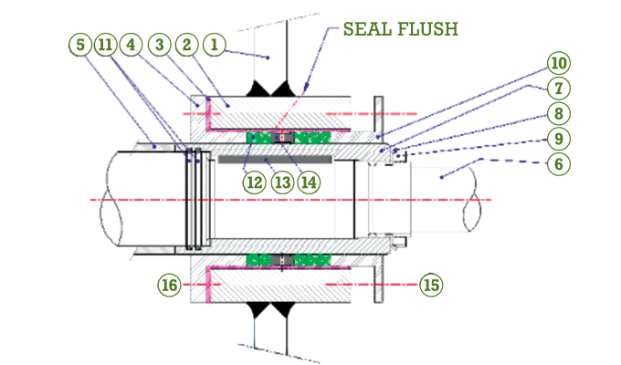
SEAL DESIGN: A CLOSER LOOK
The seal acts in the annular space between the shaft nozzle housing (2) and the rotating shaft (6). The nozzle bore is weld overlaid (3) in Stainless Steel and final machined to diameter and surface finish presenting the outer seal surface. A shaft sleeve (7) is located by a key (13), retaining washer (8) and threaded lock nut (9). This shaft sleeve is located by the breaker teeth hub (5). An inner compression ring (4) is bolted (16) to the housing. Sealing between the shaft sleeve and the shaft, preventing slurry intrusion and leakage is provided for by two O-rings (11).
FOR MORE INFORMATION
KnightHawk Engineering was founded in 1991 and specializes in getting high technology solutions in a short timeframe. At KnightHawk Engineering, we start by addressing the physics of a problem in order to create a unique solution in a timeframe our clients require. KnightHawk has assisted the largest companies in the world, NASA, and some of the major mining operations across the globe. For more information, visit www.knighthawk.com.
MODERN PUMPING TODAY, May 2020
Did you enjoy this article?
Subscribe to the FREE Digital Edition of Modern Pumping Today Magazine!