


GE Oil & Gas is developing subsea membrane-based water injection systems for improved oil recovery. The exploration and production activity in deeper waters, harsher environments and more remote locations have been a key oil and gas industry trend over the last decade. Today, subsea production could reach 3,000 meters water depth. At this depth, the ambient pressure is 4500 psi (300 bar). Over the past few years, GE Global Research has been working with GE Oil & Gas and GE Power & Water, performing high pressure laboratory flow tests of various GE’s ultrafiltration, nanofiltration, and reverse osmosis membranes at deep subsea conditions.
In these laboratory tests, water is pressurized to 4500 psi with a reciprocating triplex plunger pump. To obtain high quality laboratory measurement of subsea membrane performance, precise control of transmembrane pressure (TMP) is critical. But without a high performance dampener, this is not possible due to large pump pressure pulsation. The pressure pulsation was reduced to less than 2 psi (0.14 bar) after the installation of a Blacoh XPH pulsation dampener, enabling reliable testing and validating the performance of membranes for deep subsea applications.
The Blacoh engineering team was faced with a challenge: eliminate pulsation in a testing system to less than 2 psi (0.14 bar). The dilemma is that a positive displacement pump produces pressure and flow pulses that need to be nearly eliminated, and the formula normally used to predict dampener performance does not give very accurate results with residual pulsation levels below 2 percent. It turns out that we need to look at more than just dampener volume to obtain this higher level of performance. What are the additional factors that can lead to the desired results for high precision dampening? How can one meet these critical high performance requirements?
Featured Image: High pressure test skid (photo credit: Mick Hemberger for GE Global Research).
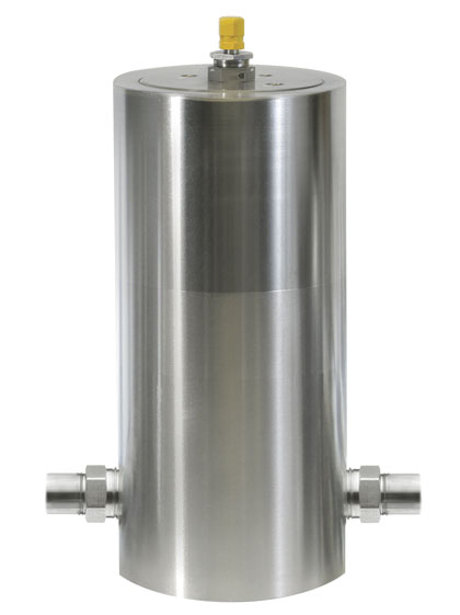
Above: Sentry XPH high-pressure pulsation dampener (photo credit: Mike Hemberger/Photographer).
THE NECESSITY OF DAMPENERS
All fluid systems are susceptible to vibrations, pulses, and pressure fluctuations whenever fluid is accelerating or decelerating. In most cases, small pressure changes occur all the time but are noticed and generally don’t cause problems. Positive displacement pumps, by nature, have pulsing flow coming out of the pump discharge. The pulses are greatly reduced by multi-piston pumps but the fluid flow is still not entirely constant. This varying flow rate means that the flow from the pump is attempting to accelerate and decelerate all the fluid in the line downstream of the pump. From fundamental physics, we learned that F=ma, force equals mass times acceleration. In a fluid system, changing the flow rate is accelerating the fluid, the force required shows up as pressure, and the mass is the fluid itself.
We have all experienced water hammer from suddenly opening or closing valves, which again is either accelerating or decelerating the fluid in the piping system. The pulses coming from a positive displacement pump are at a much higher frequency than most water hammer events, but in either case, the pressure pulses can cause damage or other undesirable effects on the system. These can include:
- Vibration in piping
- Fatigue of piping and other system components
- Damage to filter elements
- Instrumentation and pipe damage
- Inaccurate flow and pressure readings
- Hazardous or dangerous spills
- Costly maintenance
- Harm to the system and (more critically) employees
For the oil and gas industry, dampeners are needed to obtain exceptionally steady pressures and flow rates for accurate and reliable testing. Reliability is highly desirable in underwater systems due to the difficulty and expense of repairs, should any damages occur.

MYTH BUSTERS
There are many different styles of pulsation dampeners and each one has its advantages and disadvantages. There is some confusion on how these mechanical devices actually work and what performance level is possible from each style. As with most mechanical devices, the desired performance is obtained by the appropriate style and making the right choices in system design. There is no magic in engineering these systems, but small changes can make a great impact on performance.
A common type of dampener uses a flexible diaphragm that separates a gas charge from the process fluid that flows through a single inlet/outlet. This is a desirable design for most applications, as it allows for easy installation, easy removal for maintenance, and offers adequate performance when installed correctly. The disadvantage is that performance with this style is limited when required to handle high frequency pulses. It is also very sensitive to installation configuration, where distance from the discharge of the pump and length of inlet stem affect the dampening capability.
Another style of dampener is via a piston. This style uses a solid piston instead of a flexible diaphragm to separate the gas and fluid. The piston style is ideally suited for large and frequent changes in internal volume (namely surge applications), where a flexible diaphragm will wear out quickly if its range of movement is extended too much over time. The disadvantage here is that the piston has significantly more mass, which reduces its ability to react quickly to high frequencies of pulsations.
Yet another type is referred to as “reactive” or “maintenance free” style of dampener. These dampeners have a number of different arrangements of internal pipes, baffles and flow restrictors with a relatively large capacity of liquid volume to work together to reduce the size of the pulse. These units have the advantages of not having a gas charge that needs to be maintained, the ability to dampen at any pressure, and are good at removing high frequency pulses. The disadvantage is that the performance is also dependent on the compressibility of the fluid, and since fluids are only noticeably compressible at high pressures, the dampener needs to be a significantly larger size to obtain the same performance as other types.
Flow-through dampeners have a separate inlet and outlet so that all the fluid flows through the dampener. These dampeners, if they are designed correctly, generally perform very well with high frequency pulses. This goes back to F=ma again, remembering that the fluid in the inlet of an appendage style dampener needs to accelerate and decelerate with every pulse of the pump. The acceleration of the fluid through the inlet is much higher than the acceleration of the fluid in the line because it is flowing into the dampener (while the piston or diaphragm is in the discharge half of the pump stroke) and then reversing to flow out of the dampener (while the pump piston is pulling fluid in from the pump inlet).
CALCULATIONS
For a test design, we initially started with a one (1) gallon single inlet/outlet dampener with an elastomer bladder and gas charge. Theoretically this should have worked using the general formula, but pressure pulses on the 4500 psi system were still measured in excess of 20 psi – good performance for many applications at this pressure, but 10 times larger than the desired performance. The reason for the discrepancy is how the performance is calculated.
ANALYSIS OF CALCULATIONS
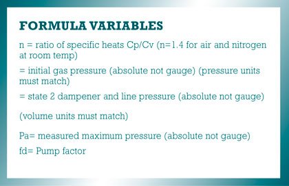
The equation that is most often used to size and calculate dampener performance is the isentropic gas compression formula described as follows:
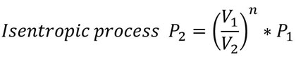
For dampener performance, we add a pump factor to the formula to account for the fact that only a portion of the volume from one piston pulse enters the dampener; the rest flows down the system piping.
However, there are limitations to the application of this formula. This formula only takes into account the compression of the gas in the dampener. For low frequencies and for general performance this formula works well. When dampened performance with residual pulsations 2 percent or less is desired we need to account for the acceleration of the fluid, the high frequency pulses, as well as the compression of the gas in the dampener.
NEW ADVANCEMENTS
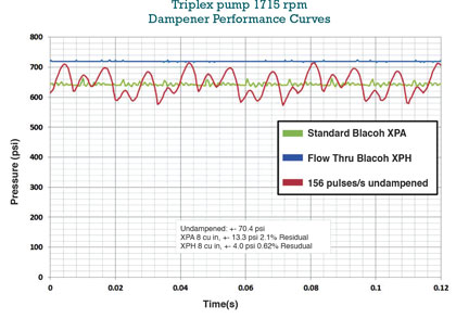
A bladder style dampener with a flow through design was chosen for testing. This dampener was designed to reduce the high frequency pulses, and the flow-through design eliminates the accelerating and decelerating flow in the outlet of the dampener and due to flow reversal in the inlet. The dampener was placed in a system and the pressure monitored by a pressure transducer downstream of the dampener. See figure 1 for a triplex pump operating at 720 psi and 1715 rpm. We observe the performance with and without the dampener, and then compared this with the performance from a single inlet/outlet style dampener of the same size. We were able to reduce the pulsations to +/- 4 psi, which was exactly what was seen when the pump was turned off, meaning that we were at the limits of the resolution of the test instrumentation. We calculated that if a slightly larger unit was added to the test system, and the existing one gallon dampener was left upstream of the flow-through dampener, the desired performance could be realized.
Dampeners are not often associated with frequency; however, there are normally high frequency / low amplitude pulses in most positive displacement pumping systems. These high frequency pulses generally bypass a standard single inlet/outlet dampener and proceed directly down the system. We have noted that high frequency pulses greater than 15 Hz tend to get by the single inlet/outlet design dampeners, and we realized that with higher frequency, the less effective the standard design is. With the flow-through design, all of the pulses go into the dampener and (if designed correctly) the high frequency pulses can be almost completely eliminated. Performance with significantly less than 1 percent residual pulsations has been realized resulting in exceptionally smooth flow.
RETURN ON INVESTMENT
Facilities are now able to obtain highly precise measurements, have precise control of pressure and essentially eliminate pulsation with the installation of a high pressure, stainless steel flow through dampener with an elastomer bladder. Having the data to prove a situation and design rather than solely basing it off of ideal conditions and ideal calculations gives reliable results and the confidence to know that the dampener will provide the right solution. Safety is a priority in all facilities, and it is inevitable over a pump system’s lifetime that there will be downtime, maintenance, and other costly equipment repairs of system failures. The use of a flow-through bladder dampener (when properly installed and charged) will reduce system vibrations, significantly improve energy savings, and in this case, remove the remaining high frequency and acoustic pulses for a well-protected pump system and exceptional performance results. ◆
For More Information:
David McComb is the engineering manager at Blacoh Fluid Control, a manufacturer of pulsation dampeners, surge suppressors, inlet stabilizers, and other fluid control products. McComb obtained a B.S. in mechanical engineering from University of California, Riverside, and has extensive experience in project and product line management. Kevin Louie is the marketing manager at Blacoh Fluid Control. Louie was previously an application engineer and holds a B.S. in aerospace engineering from University of California, San Diego, and marketing certificate from University of California, Los Angeles. Blacoh is celebrating its fortieth year as an industry leader. For more information, visit www.blacoh.com.
____________________________________________
MODERN PUMPING TODAY, March 2016
Did you enjoy this article?
Subscribe to the FREE Digital Edition of Modern Pumping Today Magazine!
![]()