The Cross-State Air Pollution Rule (CSAPR) is at the center of the regulatory debate. The EPA rule replaces the 2005 Clean Air Interstate Rule (CAIR) tightening caps on sulphur and nitrogen oxides. Regardless of the Appeals Court stay in early January, the focus on equipment reliability is now more important than ever for efficient utilization of existing pollution control technologies. In December 2011, the Department of Energy outlined “near-term compliance pathways” highlighting the need for increased utilization and reliable performance of Wet and Dry Flue Gas Desulphurization (FGD) units. Selecting reliable mechanical seals is of critical importance and is the subject of this article.
INDUSTRY CONVENTION IS OF INTEREST
Industry custom is to fit single-type heavy-duty mechanical seals in FGD applications to seal the lime slurry from exiting at the rotating shaft region of pumps and other fluid movers. The seal is often the first component to fail and seal performance can be unpredictable. How have FGD distinct operating parameters been addressed by industry standards? Standards are written collaboratively by industry experts to apply to a wide range of applications. The unique issues in FGD units encourage the plant reliability professional to produce an add-on company standard or purchaser’s amendment to assure predictable sealing performance.
The referenced single-type heavy-duty mechanical seal design (see figure 1) has a single set of precision-lapped silicon carbide components (faces) to contain lime slurry. Stability of the fluid film between the face set is essential for long-term performance. Failure margins narrow when operating conditions impact the stability of the fluid film.
The operating practices necessary for optimum FGD efficiency may adversely affect seal performance. The utilization efficiency of the FGD unit is improved with fine pulverized limestone and forced oxidation. High speed pumps are used to feed rotary atomizers (in the case of dry FGD). These variables impact the stability of the seal’s fluid film. Adding proprietary sorbents with reagent enhancers or additives and the resulting unknown fluid properties make seal performance even more unpredictable.
As detailed by Mohamad Hassibi, Chemco Systems, L.P: “For SO2 capture with ground limestone in wet FGD, much of the coarser particles never react with gases. Because of a short contact period, many of these particles are basically wasted. For limestone to react with SO2 gas there should be some dissolution of limestone so that it can ionize. Fine pulverization generally improves the rate of dissolution, thus increasing SO2 capture efficiency.” This applies to dry FGD installations as well; here, the greatly increased surface area in fine micron particles means less absorbent is required. At one facility, particle distribution sampling determined that approximately 50 percent of the particles were 8 microns or less. The small particles enter into the micro-gap between the seal faces leading to unpredictable seal performance.
Air injection is utilized to ensure a fully oxidized gypsum product. Oxidation may be through a sparging grid system or through air lances mounted near side-entering agitators. Air injection can be problematic for the seal face set. The cost of a maintenance event on large equipment can be as much as $50,000 per occurrence. Managing this cost has led some utilities to try horizontally split mechanical seals with a single set of faces. Retrofitted to existing large-bore bell housing designed seal chambers, it is believed an external flush water injection (American Petroleum Institute (API) Piping Plan 32) will protect the seal faces. However, experience-based industry guidelines state this strategy is impractical.
In dry FGD, higher speed pumps generate pressure (head) for rotary spray atomizers. In one example, a 6-inch (nominally 150 millimeter) inlet and 4-inch (nominally 100 millimeter) discharge pump was specified to operate at 1800 RPM. Pump thrust loads are balanced by back vanes (pump-out vanes) in the pump impeller. Industry practice is to modify the back-vanes to accommodate operating limitations of single slurry mechanical seals.
CONSULTING THE STANDARD GUIDELINES
The industry standard for rotodynamic equipment is the American National Standards Institute (ANSI) / Hydraulic Institute (HI) Rotodynamic (Centrifugal) Slurry Pump Standard ANSI/HI 12.1-12.6-2011. This comprehensive document is recognized as the authoritative reference for slurry pumps. Written collaboratively by Hydraulic Institute members, who are experts in the industry, the standard covers a wide range of topics. Section 12.3.8 describes general arrangement details for mechanical shaft seals. With respect to this section, a number of cautionary statements highlight the difficulties associated with predictable seal performance.
Summarizing the cautionary statements in section 12.3.8, industry practice is to use “bell housings, large tapered bore seal chambers, or large tapered bore seal chambers with vortex breakers (to) improve seal life by preventing a build up of the slurry around the sealing faces that can cause excessive erosion.” The standard goes on to state: “If air bubbles surround the seal faces, the seal can run dry, leading to seal face damage and potential seal failure . . . the slurry concentration and particle size limits (100 to 1000 microns / 0.004 to 0.04 inches for d50 particle size at 50 percent concentration) when using an external injection are only limited by the ability of the injection system to exclude the slurry from the seal chamber. The associated product dilution needed to accomplish this task needs to be assessed . . . (with) large diameter shafts this is normally not practical as the required bushing radial clearances to account for shaft deflections will result in excessive flow rates, or dilution into the product.”
The standard continues and notes: “dual pressurized seals have the advantage of providing enhanced lubrication to the faces with a pressurized barrier fluid. This arrangement prevents process fluid leakage to the atmosphere to improve safety . . . dual pressurized seals are used when the limits (of heavy-duty single mechanical seals) are exceeded, when there is a potential for entrained air in the slurry, or when large volumes of air can be introduced into the pump.”
DUAL SEAL DESIGN: A CLOSER LOOK
Figure 2 shows a dual pressurized seal design. With two sets of seal faces, the process lime slurry is contained by an inboard set of faces and a secondary barrier fluid (water) is pressurized higher than the process. The barrier fluid is contained by an outboard set of seal faces. The higher pressurization means the secondary barrier forms the inboard seal face fluid film. Constraints caused by small micron particle size and air injection are mitigated because the seal face is operating on clean and stable water.
Delivery of the water barrier fluid is important to application success. Traditional piping configurations are API Plan 53-A and API Plan 54. Plan 53-A is limited by a fixed volume of barrier fluid; a fluid-containing vessel or “seal pot” is externally pressurized by air or nitrogen. During process upset conditions, the pressurized volume of fluid crosses the inboard seal face, and the seal pot must be re-charged during operation. This re-charging process is not operator friendly, bringing a high likelihood the seal will run dry. Plan 54 is a centralized water barrier distribution system, usually through multiple pumps. This means the circulating system must always be pressurized 15 to 30 psig above any seal chamber pressures to avoid cross contamination of the barrier fluid.
HYBRID SOLUTION
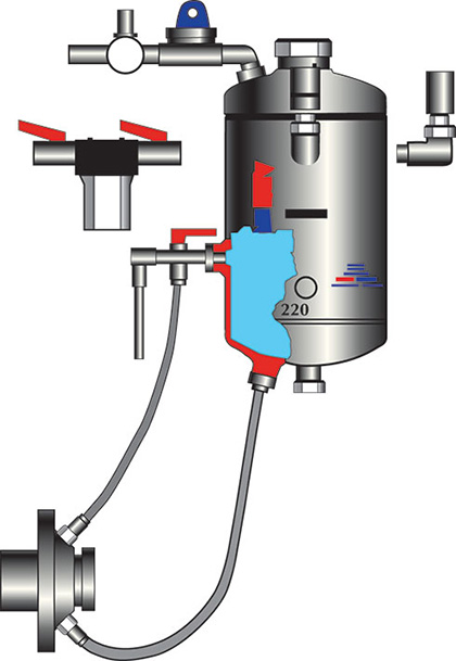
Leading user companies have success with the suggested hybrid solution; it combines Plan 53 and Plan 54 with water delivery to a water management system designed to control pressure and cool the seal faces. The system (figure 3) uses a regulator and a back-flow preventer to set the correct water barrier pressure for the seal faces.
The water is re-circulated, reducing actual consumption to just a few gallons per year. An in-line filter connected to the continuous source water filters the barrier fluid to 1 micron absolute. A three-way valve on the line returning from the seal to the reservoir enables the operator to inspect the condition of the barrier fluid in the seal without compromising seal performance. In the event any particles cross the inboard seal face, the three-way valve is activated to flush the seal. An internal standpipe on the supply line to the seal protects the seal from contaminants. By connecting a valve and drain line to the bottom of the tank, an operator can purge contaminants from the reservoir while the connected water source automatically replenishes the system with clean water.
If process air bubbles accumulate at the seal face, the secondary liquid provides sufficient cooling to ensure consistent seal performance. Independent control of the seal environment broadens the success margin for the seal. An add-on company standard or purchaser’s amendment couples specific operating conditions with available industry standards and provides for the optimum utilization of the FGD unit.
EMPHASIZING RELIABILITY
Plant reliability professionals will consider bridging the distinct operating parameters of FGD processes with existing industry standards for slurry sealing. Their add-on wording will incorporate the options outlined above; these options will constitute an important amendment to current equipment standards:
- The mechanical seal must be a heavy-duty dual cartridge mechanical seal suitable for slurry duty and designed to operate at a higher pressure than the process pressure at all times.
- Seal-internal cross-sections must have large radial clearances and the inboard face set must be hydraulically balanced to the barrier fluid.
- Tungsten carbide (TC) and/or silicon carbide (SiC) faces with solid TC must be used when the pH is greater than 5; solid SiC must be used when the pH is 5 or less. Pin drives must be designed to minimize face fracturing.
- Large pump sizes must be configured to accept a front load seal design that can be installed from the wet-end of the pump, which will minimize the cost of overhaul.
- Wetted alloys must be Alloy 255 for abrasion resistance.
- Mechanical seals must perform equally with or without impeller back-vanes and the user requests that back-vanes be incorporated in the equipment impellers.
- A mechanical seal support system must be provided as a pre-engineered turn-key system; it must include all instrumentation and fittings necessary to install at site.
- The tank capacity must be a minimum of 6.6 gallons (25 liters) and self-filling. Inboard seal face integrity must be visually confirmable at the support system with a flow indicator.
- The system must deliver barrier fluid at pressure differentials 15 psig (minimum) above the process pressure in the pump stuffing box at all times.
- The seal system must include in-line filtration of plant seal water to 1 micron. An internal standpipe on the supply leg, a three-way valve on the return leg, and a blow-off valve at the bottom of the tank must be included to allow clearing the system of any contamination after the initial installation and during the life of the application.
- As part of the initial supply package, documentation must include a heat generation report for each installation. The report must refer to the operating conditions for the intended shaft diameter, speed, process / barrier pressure, temperature and induced flow. These data must provide the input for a thermal equilibrium estimation and result in a calculation of the heat generated by the specific seal supplied in each case.
REGULATIONS AND THE FUTURE
As regulatory legislation issues persist, a compliance strategy will drive solutions for optimizing reliability of rotating equipment. This will lead to technology and revision of current standards to meet increased demand for viable solutions. While in no way pre-empting the existing standard documents, it is hoped that this article gives experience-based guidance to FGD plants. The authors encourage reliability professionals to structure add-ons or amendments based on the feedback and recommendations contained in this article.
_______________________________________________________________________
ABOUT THE AUTHOR
Heinz P. Bloch, P.E., is one of the world’s most recognized experts in machine reliability and has served as a founding member of the board of the Texas A&M University’s International Pump Users’ Symposium. He can be contacted at heinzpbloch@gmail.com. Tom Grove is executive vice president at AESSEAL Inc., one of the major specialists in the design and manufacture of mechanical seals and support systems. For more information, visit www.aesseal.com.
_______________________________________________________________________
MODERN PUMPING TODAY, June 2013
Did you enjoy this article?
Subscribe to the FREE Digital Edition of Modern Pumping Today Magazine!