In the first of this four-part article, we pointed out the importance of keeping contaminants away from lube oil in pump bearing housings. We mentioned that well-designed modern bearing housing protector seals can provide substantial ingress reductions. However, the reliability-focused user must consider the level of protection offered by a particular bearing housing seal. Not all bearing housing protector seals function the same way. As this series continues, we will examine how rotating labyrinth seals work and ask several questions of interest to the reliability-focused professional. Also, we’ll take a closer look at both industry standards and user standards for motors, applications for steam turbines, and application criteria for face-type bearing protector seals. In the end, we hope to show that by understanding the different demands of these applications, cost justification can be quite simple.
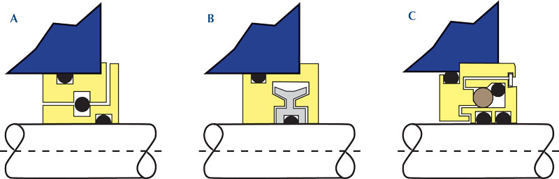
Figure 2: Three different “generic” versions of bearing housing seals. Styles with contact between O-ring and sharp edged grooves (2a) are vulnerable, especially so if rotors incorporate low clamping forces. Some styles have high drag force between the rotor and the stationary component (2b). Advanced styles with dynamic O-rings (2c) make contact with a large and contoured surface (2c). They exert low pressure and have optimally low drag forces.
ROTATING LABYRINTH SEALS: HOW THEY WORK AND HOW THEY DIFFER
It can be shown that in machinery such as the literally millions of centrifugal process pumps operating today, modern bearing housing seals make much economic sense. Findings of rapid payback and quantifiable failure reductions with bearing isolators are supported both by user industry statistics. For decades, lip seals have been out of compliance with the minimum requirements stated in the widely accepted API-610 industry standard for centrifugal pumps (see reference 6). Indeed, most rotating labyrinth seals are a good choice for fluid machine bearing protection and will often outperform lip seals by wide margins.
It must be realized, however, that there are many types, configurations or versions of rotating labyrinth seals. Different configurations will allow anything from a truly minimal amount of “breathing” and virtually zero leakage, to a rather significant amount of breathing and worrisome leakage. The amounts of breathing and leakage depend very much on the design and construction features of a given style or brand; these features must be compared against the configuration and/or construction features of another make, style, or brand.
A number of parameters are observed and compared by reliability and value-focused observers. Before deciding to buy, a value-focused observer often requests test data and cross-sectional views. Together, these data will disclose the operating principles of different versions of bearing protector seals (figure 2). Reliability professionals are not asking for the disclosure of proprietary manufacturing drawings; however, they want to see and understand exactly what it is they are purchasing. (Note that figure 2 is a generic depiction only.)
Reliability professionals are most productive when they manage to work with dependable vendors who, in essence, become their technology providers. Competent vendors and manufacturers display a cooperative attitude which then facilitates rigorous product comparisons. Although brief, a detailed review of their relevant drawings, references or patent applications will often prove revealing. For instance, some rotating labyrinth designs and configurations (such as figures 2a and 2b) are decidedly not field-repairable, while other manufacturers have thoughtfully designed “in-place repairability” into rotating labyrinth seals. Certain advanced designs incorporate both axially sliding and radially non-wearing O-rings; note that both O-rings in figure 2c are field-replaceable
Observe where the O-ring might be located in a relatively elementary seal, shown as a simplified or generic example in figure 2a. Here, the O-ring is located between rotating and stationary components. It must move radially in or out of a very close-tolerance groove.
Tight manufacturing tolerances are needed in bearing protector seals whose effectiveness depends on sliding motion of a dynamic (or moving) O-ring against the edges of a sharp abrupt groove (figure 2a). In contrast, visualize another, more modern, design that incorporates a dynamic O-ring making contact with a relatively large area (see figures 2c and 5).
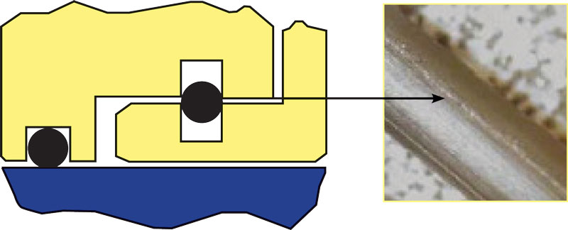
Figure 3: O-rings in contact with sharp edges are prone to wear excessively. Sometimes, slivers of the elastomer get into a bearing housing.
AREA OF CONTACT AND NEED FOR LIFT-OFF
Available area of contact is important in bearing protector seals. An O-ring contacting a very small area will show the effects of force divided by a small area (figure 3). A sharp edge has a small area. The pressure (equal to force divided by area of contact) will be much lower as the force acts on a large area than if that same force were to contact a sharp edge. A tiny amount of lubricant must be present to counteract wear, but that tiny amount is far more likely to stick to a large surface at low pressure than to a much smaller surface at high pressure.
It certainly was (and remains) the original design purpose for O-rings to seal against an applied fluid pressure. In most conventional O-ring applications, fluid pressure forces the O-ring against contacting groove surfaces and the elastomer forms a stationary seal. In hydraulic cylinders, the O-ring is often inserted in a closely dimensioned groove in the piston. When the piston is stroked, the O-ring is said to become a dynamic O-ring. Because the hydraulic fluid provides sufficient lubrication between O-ring periphery and cylinder bore, reasonably long life is usually attained.
In some rotating labyrinth seal designs—the ones similar to figure 3—the O-ring is expected to lift off radially when the shaft is rotating. But, the same O-ring is also expected to seal the small gap between rotating and stationary component whenever the shaft stops turning. Will it do that?
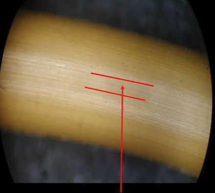
Figure 4: O-rings in contact with large surfaces show “polishing,” not wearing.
QUESTIONS OF INTEREST
Before making a product selection, several questions are of interest to the reliability-focused:
- Will an O-ring lift off as anticipated?
- As the O-ring lifts off, is it likely to make contact with sharp edges of neighboring components?
- Are all relevant components likely to stay in place, or will the rotor “walk down” on the shaft?
- Is a product field-repairable, and what is its reliability record?
- Does the bearing protector seal manufacturer have test data relating to the wear life or leakage behavior of the product?
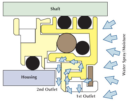
True non-contacting designs will allow an interchange between ambient and housing-internal air. Fortunately, the contamination-inducing interchange of air can be minimized by thoughtful engineering and by incorporating a multi-stage or multi-tiered design. Such a field-repairable design, figure 5, can exclude contaminants more effectively than certain simpler, traditional, rotating groove designs.
The field-repairable and compound cartridge rotating labyrinth seal design of figure 5 offers some rather unique features. Its manufacturer can provide test data and Weibull plots that indicate attractive life expectancies and virtual freedom from leakage.
Examine how figure 5 actually works: Two O-rings clamp the rotor to the equipment shaft. With the equipment in the non-running condition, an O-ring (“energizing member”) applies a radial load on a portion of the periphery of another O-ring, one with a considerably larger cross-sectional diameter. This second O-ring serves as the primary shut-off valve. When the equipment is operating, the energizing O-ring is subjected to centrifugal forces that cause it to move radially outwards and disengage it from the primary shut-off valve. This then allows the primary shut-off valve to move away from the stationary ring and the resulting micro-gap allows the bearing housing to breathe. As the equipment stops, the energizing member again takes up its idle position and axially moves the primary shut-off valve to provide a static seal with the stator.
The O-ring serving as a shut-off valve is made from a wear-resistant material with a low coefficient of friction. Tests showed that this simple, yet effective, arrangement prevents moisture droplets from being sucked back into the oil during cycles of bearing chamber breathing.
A second moisture ingress abatement feature of the seal shown in figures 2c and 5 acts as a multi-tiered terrace-like pathway system. It consists of a staggered path between the counter-rotating members; each pathway includes a series of orifice-like outlets. The pathway system creates a cascading effect and extensive testing confirmed that water intrusion is virtually non-existent. This earned figure 5 the high IP66 Ingress Protection rating.
Figure 5: Multi-tiered arrangement, tortuous path and expulsion orifices of modern, field-repairable rotating labyrinth seal. (source: AESSEAL, Inc., Rotherham, UK, and Rockford, TN).
A LOOK AHEAD
Parts 3 and 4 will highlight ratings and standards. They will also show bearing housing protector seals for small steam turbines and an example cost justification tabulated for advanced bearing housing protector seals.
REFERENCES
- Bloch, H. P. and A.R. Budris, Pump User’s Handbook: Life Extension, 4th Edition, Fairmont Press, Inc.: Lilburn, GA (2013). ISBN 0-88173-720-8.
- Adams, V., R., Barry Erickson, Bill Needelman, and Michael D. Smith, “Proceedings of the 13th International Pump User’s Symposium,” Texas A&M University, Houston, TX (1996): 71-79.
- Eschmann,P aul, Ludwig Hasbargen, and Karl Weigand, “Ball and Roller Bearings,” John Wiley & Sons, New York, NY (1985): 183, ISBN 0-471-26283-8.
- Bloch, H. P.; “Twelve Equipment Reliability Enhancements with 10:1 Payback,” NPRA Paper RMC-05-82, Presented at NPRA Reliability and Maintenance Conference, New Orleans, May 2005
- SKF Catalog 140-170, August 1988: 40 (Figure 17).
- “API-610, Standard for Refinery-Type Centrifugal Pumps,” 8th and later Editions, The American Petroleum Institute, Washington, DC.
- Derrick, R, W. Martiny, and W. McDonald, “Pulp-Coated Motors: The Effect on Motor Life,” Engineering Conference Book, TAPPI, Technology Park: Atlanta, GA (1986).
- Bloch, H. P., Pump Wisdom: Problem Solving for Operators and Specialists, John Wiley & Sons: Hoboken, NJ (2011). ISBN 978-1-118-04123-9.
About The Author
Heinz P. Bloch, P.E., is one of the world’s most recognized experts in machine reliability and has served as a founding member of the board of the Texas A&M University’s International Pump Users’ Symposium. He is a Life Fellow of the ASME, in addition to having maintained his registration as a Professional Engineer in both New Jersey and Texas for several straight decades. As a consultant, Mr. Bloch is world-renowned and value-adding. He can be contacted at heinzpbloch@gmail.com.
Heinz P. Bloch, P.E., is one of the world’s most recognized experts in machine reliability and has served as a founding member of the board of the Texas A&M University’s International Pump Users’ Symposium. He is a Life Fellow of the ASME, in addition to having maintained his registration as a Professional Engineer in both New Jersey and Texas for several straight decades. As a consultant, Mr. Bloch is world-renowned and value-adding. He can be contacted at heinzpbloch@gmail.com.
MODERN PUMPING TODAY, October 2014
Did you enjoy this article?
Subscribe to the FREE Digital Edition of Modern Pumping Today Magazine!