By Peter Sucharda, Devine & Associates, and Mark Gimson, Cla-Val Company
On March 27, 2019, the city of Hamilton, Ontario, unanimously declared a climate change emergency that threatens the city, region, province, nation, civilization, humanity, and the natural world. In doing so, Hamilton joined another 490 Canadian municipalities that have joined forces with an international movement to declare that we are in a climate change emergency. As a part of the declaration, the city developed a multi-departmental Corporate Climate Change Task Force with the main directive to investigate and identify actions that need to be taken to achieve net zero carbon emissions before 2050. The city’s climate change emergency offers nine climate change goals, which focus on infrastructure, transportation, the environment, and the way the city does business.
ELEVATION, PRESSURE, AND POPULATION
Hamilton Water, which is a key stakeholder on the Corporate Climate Change Task Force, is one of the largest energy users in the city. In 2019, Hamilton Water spent more than CDN $13 million on power costs amounting to about 6 percent of the annual budget. The city’s water distribution system is one of the oldest and most complex in Canada. It includes six water distribution systems, 1,262 miles of watermains, and 144,691 water service connections. It has an elevation of 298 feet above sea level and is defined by unique geographical features like the Niagara Escarpment and Hamilton Harbor.
Maintaining a consistent operating pressure is a difficult undertaking due to the Niagara Escarpment. This steep rock face that runs through the middle of the city across its entire breadth, bisects the city into “upper” and “lower” sections. This vertical wall ascends an average of 328 feet and presents a unique challenge in the conveyance of water at acceptable flows and pressures. The city’s distribution system must maintain a minimum operating pressure of 20 psi at ground level at all points under maximum day demand plus fire flow conditions. The normal operating pressure within the network is 40 to 100 psi. There are 145 pressure district level valves within the city of Hamilton water distribution system.
Due to this elevation change coupled with the sprawling geography of the city, the water distribution system is divided into twenty-four distinct pressure districts, both open and closed. In an open district, continuous pumping is not required to maintain pressure due to the provision of floating storage, such as an elevated tank or reservoir. In a closed district, continuous pumping is required to ensure that the required flows and pressures in that portion of the distribution network are met.
In areas where a facility such as a reservoir or elevated tank is not present, pumping station discharge head must be enough to overcome system losses and to maintain the appropriate hydraulic gradient. The placement of floating storage within the distribution system not only provides sufficient amounts of water to equalize demand, but also translates into energy savings when supplying the network via gravity.
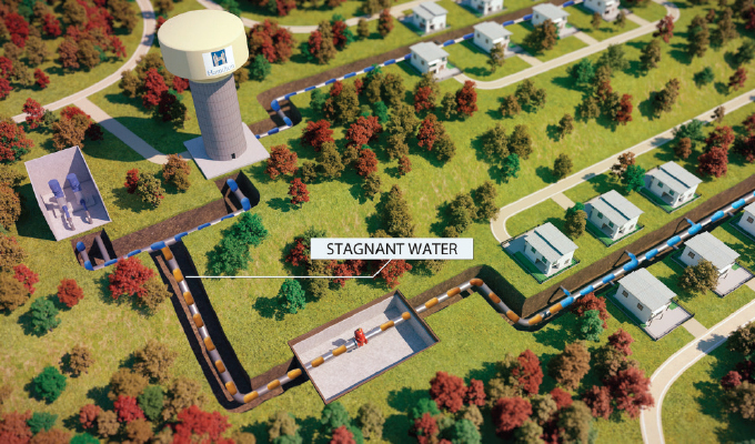
The various pressure district zones are inter-connected via level valves and an open 3/4- or 1-inch bypass line. Typically, bypass lines allow a continuous flow of water from the high to low pressure zones to provide a mixing of water to maintain acceptable residual chlorine levels. These by-passing flows consume significant pumping energy. Dave Alberton, manager of water distribution and wastewater collection for Hamilton Water, says, “Bypass lines are installed to minimize stagnant water issues at dead-ends of the water distribution system and will eliminate customer complaints. By installing the bypass lines, we solved the water quality issue but there was a cost to that continual water flowing through the line and there was no way of measuring it.”
REDUCING WATER LOSS AND ENERGY CONSUMPTION
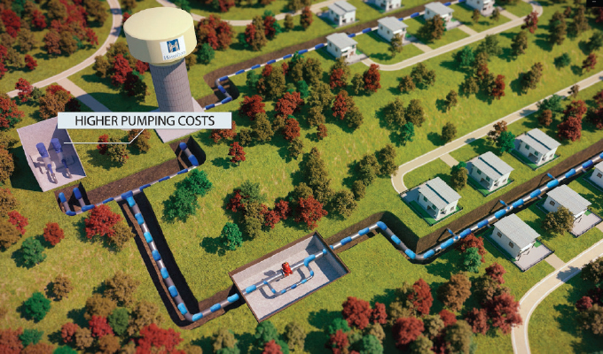
Recently Hamilton’s water distribution and wastewater collection department completed a pilot project to support the climate change initiative by reducing water loss and electricity consumption. The purpose of the pilot project was to review and investigate the significant increase in flow from two reservoirs (in Pressure Zone District 4 and 8), in comparison to the trends from previous years. This was largely due to bypass lines that were installed around normally closed boundary valves in order to keep the water fresh with a continual flow. This created three issues:
- Over-pressurization of the lower zones during periods of low demand (nighttime).
- Higher pumping costs.
- Difficulty in modelling systems because there was a great deal of water flowing through the bypass lines that was unaccounted for.
Some municipalities have tried to limit the flow through bypass lines by either throttling valves (setting them partially open) or installing a flow-limiting orifice. This inevitably causes problems because valves are not designed for throttling purposes, so it often leads to cavitation and wearing out of the valve seat. Flow limiting orifices frequently wear out for the same reasons. Also, “mini-breaks” occur within the chamber due to cavitation and high flow velocities that wear out the bypass line piping and fittings.
The city put out a tender to engineering firms which was won by Devine & Associates. “Upon further investigation with our engineering firm, we determined that it was possible to significantly reduce water flow through the bypass lines from a 24/7 continuous flow to approximately fifteen minutes per day, and still maintain water quality, by using a timer controlled anti-stagnation valve. This also significantly reduced the required water flow from pumping stations which lead to a trickle down of many cost savings,” adds Alberton.
SILENCING THE NOISE, STOPPING STAGNATION
“One issue we were having with fully-open bypass valves was noise complaints,” says Alberton. As water was passing through the bypass piping at high velocity it would create a loud noise, so the city closed the bypass lines to minimize noise complaints. Closing the bypass lines stopped the noise complaints but allowed stagnant water problems to occur.
“By installing anti-stagnation valves, flow through the bypass lines could be limited to short durations at specific times during the day. Typically, our anti-stagnation valves are scheduled to open mid-morning for fifteen minutes. At that time many people are away or busy and there is ambient noise. Previously, noise complaints were often made at night or in the early evening. Anti-stagnation valves provide the flexibility to limit resulting noise to times that are more acceptable to residents,” concludes Alberton.
Before the installation of the anti-stagnation valves, the city inspected and cleaned all thirty-seven valve chambers. All bypass lines were closed for forty-eight hours resulting in a 35 percent flow reduction leaving Greenhill Station in Pressure District 4 (from 5.28 million gallons per day down to 3.43) and 77 percent (0.79 million gallons per day down to 0.158) leaving Dewitt/Ben Nevis station in Pressure District 8. “This shutdown was done to prove that closing the thirty-seven valves decreased the flow out of the two reservoirs. We also had no pressure or water quality complaints and no service interruptions,” says Alberton.
A LOOK AHEAD: ANTI-STAGNATION VALVES
The anti-stagnation valve is a simple hydraulic control valve that is opened and closed by actuating a latching solenoid on or off. The solenoid changes state, either putting high pressure water into the valve’s control chamber (causing the valve to close) or taking water out of the valve’s control chamber (causing the valve to open). The solenoid is a low-powered device that requires only a short pulse of electricity to flip from one state to the other. The valves chosen were a 3/4-inch Cla-Val Model 139-10A, a programmable timer control valve, which is an on/off control valve that can be programmed to operate on a time schedule.
Alberton adds, “It’s easy to check-in on the valve and make changes with the interface cable that connects the anti-stagnation valve through a USB port to a computer.” Free software downloaded from the Cla-Val website, is used to communicate to the valve. Once connected a person can check the valve’s position status (open or closed), test the valve by forcing the valve open or closed, determine the valve’s battery level, automatically update the unit’s date/time by synching to the computer, and of course set when the valve opens/closes.
“The valve can open up to twice a day, but we normally set it to open once. Like a sprinkler timer, the unit can be programmed to open every day or every other day or specific days of the week,” says Alberton. In next month’s conclusion, we’ll walk through the installation of anti-stagnation valves for the city of Hamilton and the implications this has for other cities.
FOR MORE INFORMATION
Peter Sucharda, P.Eng., is president of Devine & Associates, which works with end users, consultants, and contractors to design, produce, implement, and support flow solutions for water, wastewater, storm water, slurry, and other fluid applications. He can be reached at psucharda@devineassoc.com. Mark Gimson is director of marketing and international sales for Cla-Val Company and can be reached at mgimson@cla-val.com. Cla-Val is a world-leading designer and manufacturer of automatic control valves. From reducing and relief valves to deluge, air valves and more, Cla-Val manufactures and provides a wide variety of solutions for use in some of the world’s most demanding applications. For more information, visit www.cla-val.com.
MODERN PUMPING TODAY, August 2021
Did you enjoy this article?
Subscribe to the FREE Digital Edition of Modern Pumping Today Magazine!