By Pat Phillips, AutomationDirect
In the first part of this series, we laid out the four basic pneumatic circuits as well as the prerequisites for implementing pneumatic design best practices. Below, we’ll take a closer look at different circuit designs and the benefits they can provide to various applications and larger pneumatic systems.
DOUBLE-ACTING CYLINDER CIRCUIT
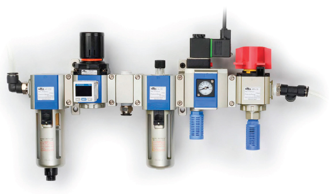
Automation to extend and retract an air cylinder is common in many machines. Figure 3 shows a pneumatic circuit consisting of a four-way solenoid valve (SOL01) operating a double-acting cylinder (CYL01). Filtered air from the air preparation unit feeds a solenoid valve controlled by a PLC.
The solenoid valve symbol SOL01 indicates it is a single-acting, spring-return valve. This valve is pilot-activated, indicated by the triangles at each side of the symbol. These pilot valves are efficient, using a small amount of air to move a large valve spool. However, a minimum amount of air pressure is required to move the spool. This minimum operating air pressure is noted in the valve specification, typically about 20 psi is needed to ensure the valve operates as designed.
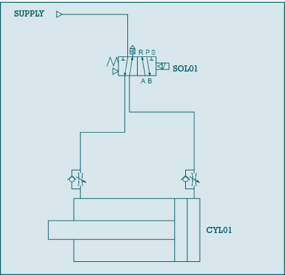
As depicted in the symbol of SOL01, a spring on the left side pushes the valve spool to the right when in its normal resting state, off. With the valve off, air is supplied out of port A and flows through an adjustable flow control to the left side of cylinder CYL01, retracting the cylinder. While the cylinder is retracting, air on the right side of the cylinder exits through a flow control device. The check valve around the adjustable flow control device closes, forcing air through the adjustable flow section of the device. These adjustments can be used to throttle the cylinder retract speed. The flow-controlled air then flows through port B of the valve, then through a muffler at port S.
Typically, a valve such as SOL01 is energized by a 24 VDC PLC output. This switches the valve, supplying pressure out port B. Similar to the normal resting state flow, this air flows freely through the flow control to the extend side of the cylinder, extending the cylinder rod and plunger to the left. The air on the left side of the cylinder is forced out thought the flow control. As the air exits to port A of the valve, the flow can be controlled. The air then flows through port A to port R, where a muffler is installed to reduce the exhaust noise.
CONTINUOUS CYCLING CYLINDER CIRCUIT
With no external control required, figure 4 provides a circuit example of how pneumatic components alone can be combined in a well-thought-out design to automatically cycle by simply supplying compressed air to valves VLV02, VLV03, and VLV04.
With compressed air supplied, when solenoid SOL01 is energized with CYL01 physically retracted, the system will start cycling, extending, and retracting cylinder CYL01. In this condition, supply air flows through VLV04, and SOL01 then provides pilot air to directional control valve VLV02. The air supplied through VLV02 causes the cylinder to extend and retract (cycle) in a similar fashion to the double-acting cylinder discussed in figure 3. To control the cycle speed of the cylinder, flow control valves are used to adjust the flow of air exiting the cylinder.
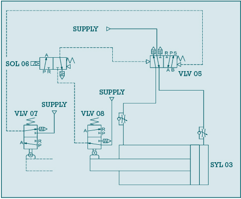
As cylinder CLY01 extends, it physically operates the three-way, two-position spring returned valve VLV03. This valve supplies pilot air to VLV02. The pilot air switches the position of VLV02’s spool, which reversed the direction of CYL01, retracting it. With the cylinder retracted, VLV04 is actuated, supplying pilot air to the other sided of VLV02, causing the cylinder to reverse direction and extend. The cycle repeats until SOL01 is de-energized. Once de-energized, the cycle ends once the cylinder retracts.
The key pneumatic logic components of this circuit are the four-way air-piloted valve (VLV02), which is the directional control valve, and the two three-way roller-actuated valves (VLV03 and VLV04), which do the same job as electrical solenoids to control the spool position of VLV02. Instead of electricity, pilot air alone controls VLV02. VLV03, and VLV04 are configured like limit switches with a mechanical arm. Cams or flags on the cylinder are used to actuate the valves. When not activated, the valves spring return to their normal position.
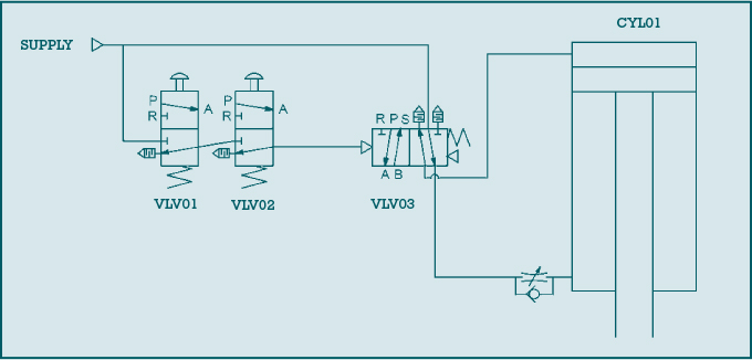
TWO-HAND CONTROL CIRCUIT
The pneumatic circuit in figure 5 details a pneumatic two-hand safety control system for a press application. The circuit combines pneumatic buttons VLV01 and VLV02 configured as 3-way valves. These valves feed pilot air to a four-way valve, VLV03. This circuit also highlights how small valves, the pneumatic pushbuttons, can use pilot air to operate a large valve controlling a large press cylinder with high air flow requirements. Although not shown in this circuit, anti-tie-down checks could be added to further improve the safety of this design.
Both pneumatic buttons must be pressed simultaneously to cascade pilot air to the directional control valve VLV03. The supply of pilot air switches the valve spool, causing the double-acting press cylinder CYL01 to extend. When either push button is released, the spring return function of VLV03 switches the spool back to the normal position, supplying air to the retract side of the press cylinder.
While only one button must be released to retract the press cylinder, if either pneumatic pushbutton is tied down (held pressed), only one button could be used to operate (extend) the press. This would not be safe. In most systems with high press force, additional safety systems would need to be added to check that both buttons have been released after each cycle, and then that both buttons are pressed at the same time, within about a quarter of a second, before supplying pilot air to the direction valve VLV03. Control reliable features could also be added to ensure a single failure doesn’t allow the system to operate unsafely.
As discussed above, one-way flow control valves throttle the air exiting the cylinder to control the speed. While only the press extend speed is controlled in this circuit, a second speed control could be added to control the retract speed.
An important note when controlling air exiting the cylinder is that air must be present to control the speed. If all the air is exhausted due to an emergency stop or idle air leakage, the cylinder may move very fast the first cycle. To eliminate this problem, sometimes the flow of air into, instead of out of, the cylinder is used to control its motion.
Additional upgrades to this circuit, not shown, include adding a pressure regulator to control the extend pressure (force) of CYL01. A pressure switch could also be added for error-proofing. The switch would sense that minimum press pressure was met and provide a press force okay signal to a PLC, for example.
The variety of pneumatic circuits is endless, but these four basic pneumatic circuit examples show how common pneumatic components can be combined to perform useful automation functions. With a little imagination, FRLs, valves, flow controls, cylinders, buttons, actuators, and other pneumatic components can be combined in a variety of ways to meet the needs of almost any pneumatic system.
FOR MORE INFORMATION
Siemens Digital Industries Software, a business unit of Siemens Digital Industries, is a leading global provider of software solutions to drive the digital transformation of industry, creating new opportunities for manufacturers to realize innovation. With headquarters in Plano, Texas, and over 140,000 customers worldwide, we work with companies of all sizes to transform the way ideas come to life, the way products are realized, and the way products and assets in operation are used and understood. For more information, visit www.sw.siemens.com.
Pat Phillips is product manager of fluid power and mechanical products for AutomationDirect. In business since 1994, AutomationDirect is a distributor offering thousands of industrial automation products for electrical control systems, including PLCs, operator interfaces, AC drives, motors, stepper systems, sensors, motor control, enclosures, and more. Their prices are typically well below the list price of more traditional automation companies because of their model and focus on efficiency, and the majority of their products are stocked for same-day shipping. For more information, call 800.633.0405 or visit www.automationdirect.com.
MODERN PUMPING TODAY, October 2019
Did you enjoy this article?
Subscribe to the FREE Digital Edition of Modern Pumping Today Magazine!