The ability to separate “busy at work” from paying attention to the warning signs of rotating machinery may create confusion for some people. The warning signs must be attended to first and foremost due to the costs associated with maintenance as a whole. For many people, however, the obvious problems of a mechanical seal failure sometimes trick operators into thinking the system needs only minor attention. But there are imminent failure indicators for most pumps and rotating equipment. In many cases, seal failures are a symptom of a larger failure waiting to happen.
MONITORING LEVELS
Before addressing the warning signs of imminent failure, it’s important to understand the data pump users can collect to help them assess their rotary equipment. Currently, there are three primary sources of information pump users rely on to monitor the integrity of rotating machinery. They are as follows: vibration, temperature, and power consumption.
Vibration
The vibration readings are taken in the horizontal position (parallel to the ground), the vertical position (90 degrees from horizontal), and—in the third and most critical dimension—axial (down the long axis or centerline of a shaft/machine). Horizontal readings detect the physical movement of machinery from left to right. Vertical readings detect the physical movement of a machine from the ground up through the highest point of a machine. Axial readings allow maintenance to detect the linear movement occurring in a machine to find cavitation, misalignment, bearing looseness, bearing failure, premature mechanical seal failure, internal pump wear related to changing thrust loads (hydraulic unbalance).
Every machine has its own signature of vibration frequency, or baseline. In every situation, operators should study the newly installed machinery and record the baseline readings when the machine has achieved normal speed-temperature and load.
The general misunderstanding is not how much a machine can take before it’s time to interrupt the process and maintenance is dispatched to intervene. The objective for vibration is to detect and proactively react to any change in the machinery contrary to its known base-line history to discover the what, why, when, and how the change occurred.
Temperature
The primary purpose for knowing machinery temperature is for the proper calculation of thermal growth for mechanical alignment values. In most facilities, maintenance is responsible for retrieving thermal growth data from the OEM (original equipment manufacturer) or engineering. A contractor may develop targets of its own out of necessity through formulas and physically monitoring the warm-up cycle of a machine.
The second purpose for knowing machinery temperature is related to baseline and known operating levels of safe operating limits for bearings, elastomers, and mechanical seals. Our focus is on the following:
- Cooling water systems
- Oil cooling systems
- Air cooled fan systems
- Seal cooling systems
- Balance line temperatures
- Seal flush systems
Electrical Power Consumption (Amp Load)
Rotating machinery driven by an electric motor may fail by electrical default. One of our best troubleshooting indicators for machinery failure is an electrical trip or automatic shut-off due to overload.
Immediately, we disconnect the motor from the pump or driven machine for two reasons. The uncoupled pump is much easier to evaluate while uncoupled due to our need to slowly rotate the shaft by hand feeling for a rub, to perform shaft to bearing lift checks, and to verify thrust end play. Also, the motor may be run uncoupled under no-load condition and evaluated for electrical consumption solo. A motor which uses 30 percent or less than its full load amps (FLA) is generally considered worthy and not the source of the unexpected outage.
Furthermore, amperes and pump discharge pressure combine to offer maintenance valuable troubleshooting information regarding the performance of rotating machinery. Operational/accurate gauges and amp meters at the machinery console are invaluable tools for early interpretation and quality diagnostics at the pump.
Finally, machinery protected by DCS digital computerized diagnostic control systems may not require the coupling be removed as the data history will indicate a precise source for the outage electronically. It’s important to note this safety precaution: Never run a motor with the coupling center member (spool) assembled to the motor alone. Remove the center member every time to solo operate a motor.
WARNING SIGNS OF IMMINENT FAILURE
The more closely operators are able to measure vibration, temperature, and power consumption, the better able they will be to detect the warning signs. For example, a clear warning sign is that the pump begins to show high bearing temperature. Some of the signs to look for related to high bearing temperature would include:
- The PM/PDM cycle is too far apart for the oil to handle the load and is breaking down.
- The oil level was allowed to get too low or there was a leak.
- The oil was contaminated by steam, product, dirt or rain.
- The pump is worn out internally generating high thrust loads due to hydraulic unbalance.
In the case of hydraulic unbalance, do not waste money for parts, labor, and downtime. The recommendation would be to remove the pump for a complete overhaul.
Another warning sign would be if the pump begins to experience back-to-back mechanical seal failures. This could result from the mechanical seals are being improperly installed or something more serious—for example, the seal flush system has lost flow, is plugged off, or the pump clearances have eroded to allow the flush to follow the path of least resistance (meaning that one seal takes all of the available flush).
Furthermore, if the pump clearances have become too worn and too excessive to provide sufficient seal chamber pressure to maintain the mechanical seal in a constant fluid capsule, then this is a major concern. It is also possible that the pump shaft is too poor to maintain seal integrity.
If the pump vibration goes in and out of the A-2 Alarm range, then this is yet another warning sign of imminent failure. It may be the result of the pump cavitating due to low flow condition, the pump has sheared a pin inside the pump case allowing a case ring (stationary part) to spin with the rotating element (intermittent vibration common to equipment damaged by low flow condition).
Another potential cause would be loose parts or product solids pulled into the suction eye of the impeller, which may dislodge during shut-down and reappear after a short run-time when the machine is at full operational flow rate. Such debris moving inside the pump would account for the wide variation into and out of the A-2 Alarm range.
The final category of imminent failure warning signs is if the pump increases in mechanical clearances—for example, if the throat bushing, throttle bushing, balance bushing, or center bushing clearances are found to be twice the factory preset tolerance limits.
Other measurements that should raise concern include:
- The impeller wear ring to pump case ring clearances exceeds 0.035 inches (0.889 millimeters).
- The mechanical run-out in a pump shaft exceeds 0.003 inches (0.076 millimeters).
- The mechanical clearance in the bearing land fails to control the thrust bearing integrity.
- The seal flush flow rate is well below the engineered rate, and there is no other source or port for increasing the flush gallons per minute rate.
For many of the warning signs listed in this section, changing parts may not be the answer to resolving why the pump failed to begin with during the unexpected outage. Early detection and quality troubleshooting will help avoid investing maintenance dollars into a lost cause. Pumps with major mechanical issues cannot be saved by changing seals, bearings, or coupling shim packs.
MEASURING QUALITY LIFE CYCLES
To accurately measure the life cycle of rotating equipment, it’s important that operators familiarize themselves with different benchmarks and the responsibilities that spread throughout a facility’s structure as time goes on. For example, as rotating equipment matures, more decisions need to be conferred with management and budgeting.
As the “full life” state of a machine’s life cycle approaches, the need for material change is driven by apparent wear, corrosion, erosion or obvious defects due to the process and conditions involved. We should establish a goal to a maximum of three adjustments in machinery to achieve maximum run-time and profitability during the life-time of a capital asset.
Mechanical Seal compatibility with the pump and process is the limiting factor in attempting to improve the mechanical expected life of rotating machinery such as, “charge pumps.”
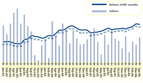
For “world class” life cycle results, the overall cycle for achievement from our current state of forty-nine months reliability to seventy-two months may require the planning period to encompass a five to six year goal.
TRENDS AND DECISIONS
When we work with refineries, we recommend facilities operate with a redundant back-up system for nearly every piece of critical machinery. Otherwise, the tendency has been to panic because one of the assets was off-line for maintenance leaving the refinery at risk for shut-down. Consequently, the availability of a spare asset has become a crutch allowing the migration of errors to creep into the mechanical process. The spare pump has evolved into a refinery with only one reliable unit available at any given time. The second asset is now a back-up to the primary asset.
Our goal is to prove to operations we can provide two full-time reliable assets for rotational and maintenance purposes creating a stronger base of mechanical integrity for the client. Previously, one mainline pump and a back-up pump was worth twenty-two months of run-time.
For a future program, two mainline pumps with equal expected life cycles of five years producing not five years individually but ten years of reliability as a pair. The decision to overhaul machinery must include the planned stagger of expiration cycles for all rotating machinery.
RE-START THE CLOCK
A quality maintenance program would not be complete if the players involved thought they had achieved the best run-time possible. The measure of our achievements is based upon the comparison to world class competition as stated by the industry through oil and gas publications or refining journals.
We must never become complacent. We must be the trend setters, the innovators, and the performers in pursuit of excellence through documented achievements. Only those professionals who understand that “good enough” doesn’t exist will recognize the early warning signs to prevent imminent mechanical failures.
_______________________________________________________________________
ABOUT THE AUTHORS
Steve Reynolds is the quality control manager for Texas Rotating Equipment, Inc. of Dayton, Texas, a leader in turbomachinery related products and services. He can be reached at 936.258.3090 or sreynolds@texasrotating.com. For more information, visit www.texasrotating.com.
_______________________________________________________________________
MODERN PUMPING TODAY, April 2013
Did you enjoy this article?
Subscribe to the FREE Digital Edition of Modern Pumping Today Magazine!